Convert BeamViz to Instrument
Overview
This command allows you to insert Spotlight Lighting Devices or instrument symbols for each of the beams.
Instructions
A dialog will ask you to match each field angle with a symbol in your document. There is also a set of symbols whose field angles are close to your selected beam.
Set any additional options to control the conversion process. See an explanation of each option below.
Click OK
Any channel and purpose data entered into your BeamViz objects will be transferred to your Lighting Devices, along with focus, hanging height, shutters, bottle rotation, and all the default values from the symbol’s Light Info Record.
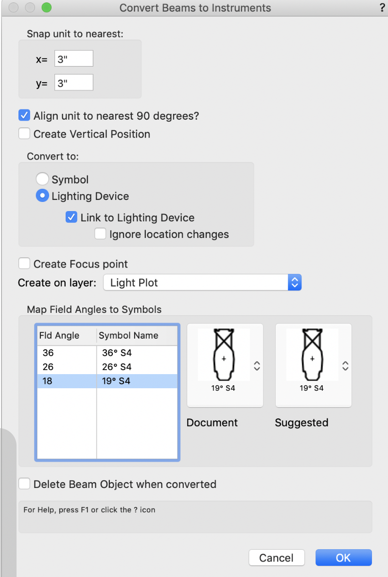
Options
- Snap unit to nearest
Aligns the insertion point of the light to a snap grid. Use a value of 0 in x or y to leave that coordinate as is. For example, if the y coordinate snaps to positions at their true location, but the x coordinate should be at regular intervals.
- Align unit to nearest 90 degrees
The light will be placed so that it aligns to the nearest cardinal direction. This is standard drafting practice for most theatrical plots, while television plots would leave this option unselected.
- Create Vertical Position
Select this item for vertical positions that do not use schematic views. After exiting the dialog, BeamViz prompts you through the process of translating those units to an elevation view. See Working with Vertical Positions
- Convert to Symbol / Lighting Device
While you will likely want to convert directly to Lighting Devices, you can place symbols instead.
- Link to Lighting Device
Create a link between the new Lighting Device and the beam. The link will cause bidirectional updates of location, focus, and paperwork data.
See Link Buttons
- Ignore location changes
When lights are not drawn in their true plan location, such as units offset for clarity or vertical positions, this will synchronize focus and paperwork data, but not hanging location.
- Create Focus Point
You have the option to create a Spotlight Focus Point at the focus point for each beam.
The Convert command will first look for existing focus points at the given focus location, and if found, assign the Lighting Device and BeamViz Object to those Focus Points.
- Create on Layer
You can select any layer onto which Lighting Devices will be placed, which may not be the same layer as the BeamViz objects.
If you have moved the beams for each system to a layer (highly recommended), this option facilitates building the finished plot on a single layer.
- Map Field Angles to Symbols
Up to this point, BeamViz has only been concerned with the spread of your light, and not your specific instrumentation.
For example, a 19° field angle might represent a narrow PAR, a zoom leko, a fresnel, an LED leko...
Before executing the dialog, you must map each Field angle to its corresponding symbol.
- Delete Beam Object when converted
You likely do not want this option, keeping a record of your worksheet to review before focus
Working with Vertical Positions
To map beams of different hanging heights to an elevation view, BeamViz requires additional user interaction when exiting the dialog.
Here is an example of the process.
We will take the 6 sidelights drawn here in true plan location and convert them to a ladder position. The ladder position will be presented on its own plate, as such it is drawn straight up/down on the page. The other common way of approaching this is ‘folding’ the position back on the page. This ladder is 3 rungs tall at 1’-9” spacing. The trim height is +18’-0” from the stage to the center of the bottom rung.
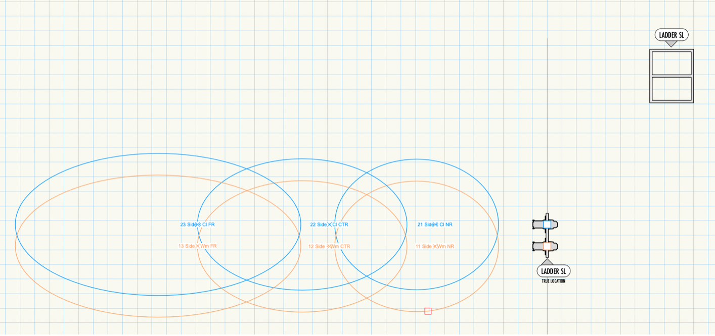
As usual, highlight the BeamViz objects you would like to convert and select the menu command to Instrument
In the dialog, ensure Create Vertical Position is checked.
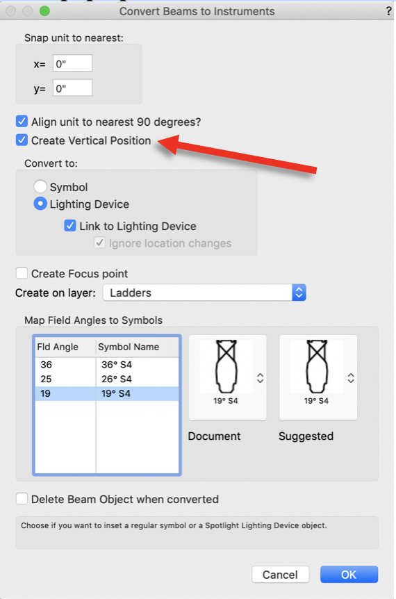
After clicking OK, you will be prompted to select the direction of your vertical position. The first click will initiate the process.
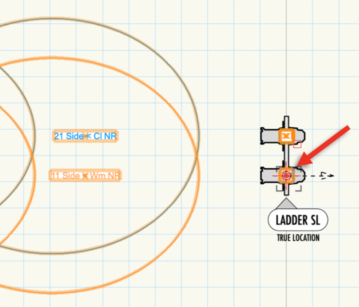
Click on the origin of the position.
The second click will point the arrow in the direction of the position.
In this example, because the ladder runs US/DS, we click above the ladder.
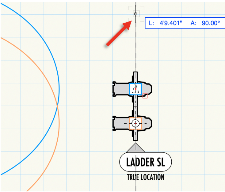
The third click will set the direction in which the lights are drawn on the position. You will see an arrow pointing in the direction of the elevation view.
We want our DS-most unit on the right-hand side of the page, so we point the arrow towards the stage left.
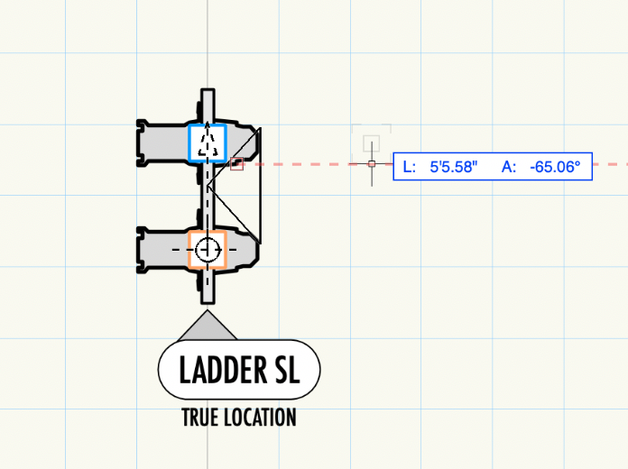
You will now see a preview of dashed boxes representing instruments drawn when you move your mouse around.
Since the ladder trims at 18' off of the deck, the lights will appear 18' above the cursor. Hover the mouse underneath the position at your 0'-0" height and line up the boxes.
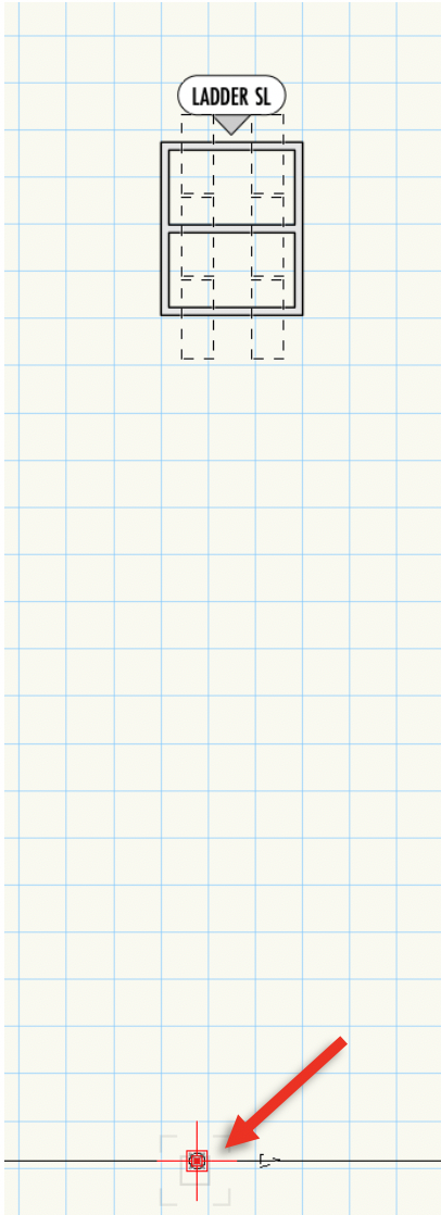
Now click, and you will have the option to rotate the lights if you need to. Depending on the view orientation, you may have to rotate the 180° while placing. You can also rotate to a position drawn diagonally.
Clicking again will draw the lights.
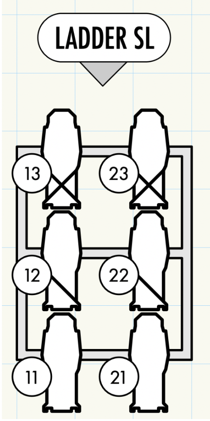
The lights are now drawn on your ladder!
