Adjusting Parameters
The BeamViz object's parameters are organized into categories, described below
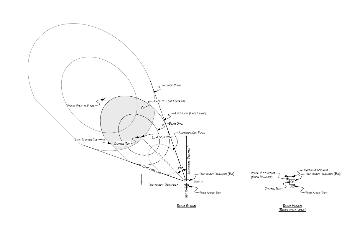
Terminology
Location
- Hanging Height
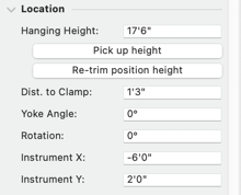
You will want to make sure your beam is being calculated from the correct height with the Hanging Height parameter.
- Pick up Height
If you have lighting positions with z height values, press the Pick up Height button to detect the height.
- Re-trim position height
Use Re-trim position height to change the hanging height while maintaining tilt / angle to face, adjusting the plan distance. Some use-cases include maintaining side light angles when duplicating beams to electrics of different trims, or transferring shows to venues with different trim heights.
- Distance to Clamp
Use Distance to Clamp to drop (positive distance) the origin of the beam below the position to its focal point. When adding a BeamViz object to a Lighting Device, BeamViz uses the Lighting Device’s 3D geometry to determine this value.
- Yoke Angle
Yoke Angle determines how the light hangs, with 0 being a normal, underhung unit, 90 yoking straight forwards, and 180 overhung. When changing the Yoke Angle, the location of the focus point remains constant, adjusting tilt, throw, and angle to face accordingly.
- Rotation
The Rotation parameter sets the orientation of the light as it hangs, and is from where the pan will be measured. In Top/Plan view, the box will have a line indicating the beam's rotation. This becomes useful for 3D visualization.
- Instrument X / Y
The object's x/y coordinates represent the focus point. The coordinates of the light are found under Instrument X / Y.
Focus
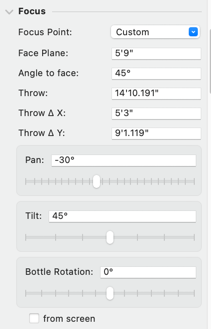
These fields relate to the focus area. All fields can receive user input, which will alter the location of the focus point.
- Focus Point
If you have any Spotlight focus points, they will appear in this drop-down. BeamViz will adjust its focus point to that location and face plane height. It will also auto-populate the ‘focus area’ field with the point’s name.
Moving the focus point will update the BeamViz object, however, changing the Beam's focus will set the Focus Point to Custom.
- Face Plane
sets the height of your instrument’s focus and is the main cut plane for BeamViz objects, which appears in Top/Plan view. Under Focus Area, you can also specify an additional cut plane at any height (even negative) and select an option to show the beam at floor level.
- Angle to face
is the angle from the face to the light. Straight top light is 90°. Changing this value will adjust the beam based on the Interaction Locks settings.
- Throw
is the distance from the light to your focus point. Changing this value will adjust the beam based on the Interaction Locks settings.
- Throw △ X / △Y
is the plan distance from the light to the focus point.
- Pan / Tilt
The Pan/Tilt sliders will focus based on the Interaction Locks settings.
Pan is relative to the beam rotation parameter, with 0° in the +y direction.
Tilt has 0° pointing straight down.
- Bottle Rotation
is available when Optics are set to PAR mode, and will rotate the beam around its throw axis.
Optics
- Instrument Type
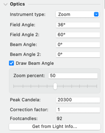
Select which type of fixture you are visualizing: Standard (Fixed focus leko), PAR (elliptical beam), or Zoom.
- Field / Beam Angle
The spread of the beam from the manufacturer's spec.
- Field / Beam Angle 2
For PAR and Zoom fixtures, set the horizontal spread or the wide range of the zoom, respectively.
- Draw Beam Angle
Allows you to hide the Beam Angle representation for this light, without setting to 0 or hiding the class
- Zoom Percent
Only displays when the Optics are set to Zoom.
The percentage from the small to large spread angles.- Peak Candela
Center Beam Candlepower, used to calculate illuminance at the focus point
- Correction Factor
Adjusts the calculated illuminance based on a lamp spec or a rule of thumb to account for gel, dust, age, etc.
- Footcandles
A read-only calculation of the illuminance at the focus point.
- Get Light Info Data
Use the Get Light Info Data button to access the beam angles, field angles, and candlepower stored in the Light Info Record of your symbols.
The symbols that shipped with Spotlight as well as those commercially available, like Soft Symbols, have photometric data already attached to them.
Use the Apply Light Info to Beams menu command to apply Light Info data to more than one beam object.
Focus Area
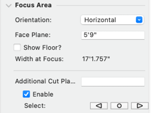
Specify the cut planes for the beam. The Face Plane passes through the focus point.
You see the cut planes as polylines in Top/Plan and NURBS in 3D views.
- Orientation
relates to how the beam is cut, or how 2D the oval is drawn. Horizontal is the default option, it cuts the beam straight across at the face plane. Aligned cuts the beam on a plane perpendicular to the beam at the focus point.
- Face Plane
sets the height of your instrument’s focus and is the main cut plane for BeamViz objects, which appears in Top/Plan view. Under Focus Area, you can also specify an additional cut plane at any height (even negative) and select an option to show the beam at floor level.
- Show Floor
will show the beam at the 0'-0" plane.
- Width at Focus
refers to the width of the beam at the focus point. This is read-only.
- Additional Cut Planes
Draws a cut plane at any height. Useful for checking obstructions or coverage at unusual heights. Use a negative value to view a plane below the 0'-0" plane, for example, to cut off the audience below the stage level.
BeamViz supports unlimited additional cut planes, and you can toggle between them using the navigation arrows.
Display Options
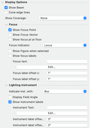
You have a number of options controlling the graphical information displayed in the BeamViz object.
- Show Beam
Deselecting this option will hide the beam and indicate the beam’s pan and channel at the hanging point, and can be a useful feature for creating rough plots.
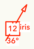
- Cone Edge Lines
Draws the extent of the beam from origin to focus in Top/Plan view. The cone-edge lines adjust to your shutter cuts.
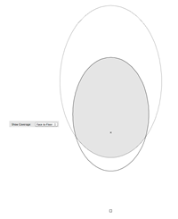
- Show Coverage
Shows the full coverage of a beam from one cut plane to another. Showing from Face Plane to Floor Plane, for example, will show you the area of full body coverage. The options are: None, Face to Floor, Face to Additional, and Additional to Floor
Focus Display
- Show Focus Point
Draws a locus at the focus point (center of beam at the face plane). The focus point can also be shown at the floor. The indicator can be changed to a symbol by using the drop-down.
- Show Focus Vector
Draws a line from the source to the focus point. Applies to both 2D and 3D views.
By default, this only draws when Show Beam is selected. You can change this behavior in Settings, which may be useful for television-style plots.
- Show Focus Point at Floor
Displays a locus at the focus point on the 0'-0" plane.
- Focus Indicator
Defaults to locus, but can be changed to any Symbol using the drop-down.
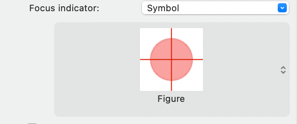
- Show Figure when selected
When the BeamViz is selected, draws a 3D Figure from the floor to the focus point (at the face plane).
- Show Focus Labels:
Input any text into the Focus text field, or use the Edit… button to append / prepend that text with any Beam information, such as Channel or an X/Y coordinate. This is potentially useful for streamlining focus charts.
The Focus Label can be offset using the Focus label offset parameters below.
Currently, the default alignment is top-left justified, to change this or the label’s font, the focus label’s class must have an assigned default text style.
Lighting Instrument Display
- Indicate Instrument with
Box — a square/cube at the source of the light
Locus
Symbol — any user-selected symbol
When using a Spotlight-ready symbol of a lighting fixture, the 3D components adjust to the beam’s pan and tilt. This can be useful when rendering or for checking the clearance of tightly packed units.- Display Field Angle
Displays the Field Angle next to the unit
- Show Instrument Labels
Displays any text beside the instrument. Input any text into the Instrument text field, or use the Edit… button to append / prepend that text with any Beam information.
The Instrument Label can be offset using the Instrument label offset parameters below.
Shutter Cuts & Iris
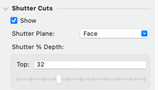
You can adjust shutters with sliders that show you real-time adjustments. This option is perfect for visually matching cuts to scenery.
You can also drag shutters via a control point right in the drawing or enter a depth and rotation in Obj Info.
In 2D All shutters are dragged on the selected plane, however, in 3D a shutter control point to snap to an object on any plane. This is useful when cutting to a multi-tiered set.
- Show
Select for the ability to specify shutter cuts. If you hide cuts, the shutter parameters will still be retained.
- Shutter Plane
Allows you to choose where shutter cut control points display in the drawing. Choose between Face, Floor, or your custom cut-planes.
- Shutter % Depths
The percentage to push in a shutter, entered as a number or by using the slider. 100% is at the focus point. You can also use control points in the drawing to drag shutter cuts.
- Shutter Angles
The rack of each shutter. The angle measures from the center of the shutter path.
- Use Screen Angles
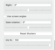
Allows you to specify shutter racks based on the top / plan angle you want for the cut. Disabling the option shows you the angle of the cut with respect to the actual gate, providing more accurate previsualization of your shutter cuts.
- Gate Rotation
A slider allows you to rotate the entire gate of the unit +/- 45º. If you need a greater rotation, enter the number in the field.
- Reset Shutters
Pulls out all the shutters.
- Iris %
A slider adjusts the size of the beam based on percentage,100% is open.
Resolution

- Resolution
BeamViz optimizes both 2D and 3D geometry, so you can generally leave this setting on High.
- Factor
Set the resolution for the Low Resolution option. Fifteen is a fairly full resolution. Four should be the minimum.
Rendering Options
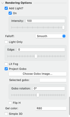
Render lights
BeamViz includes features that assist in lighting for presentation renders.
- Add Light
Select Add Light to include a rendering light that matches the beam’s parameters. The Light is also accessible in the Visualization Palette.
- On
Equivalent to toggling the light in the Visualization palette.
- Intensity
Controls the intensity as a percentage.
- Falloff
Sets how the intensity diminishes over distance
None — No change
Smooth — Arithmatic
Realistic — Logarithmic- Light Only
The Light Only option will hide the BeamViz cone, more clearly showing the rendered light source. This setting has no effect on the 2D component.
- Edge
Takes the light off sharp, adding a blur to shutters, iris, and gobos
Move the slider to the left for barrel-in and to the right for barrel-out. This works in all render modes.
- Lit Fog
Simulate haze or fog for the beam.
To see the effects, you must be using a Renderworks Background with fog enabled. Selecting this option will automatically create a new Background if necessary. Edit in the Resource Manger to adjust the fog level and type.
- Gel Color
Input a gel color to apply to the rendered beam. Specify the color by the first letter of the manufacturer and a number, e.g., L161. A dash is optional.
Colors will pull from the Vectorworks color library. To adjust the color, use the attributes palette to edit the named color corresponding to the gel id.
Gobo projection
- Project Gobo / Choose Gobo Image...
Project in image as a gobo (a.k.a. template or pattern). The selection dialog allows you to choose an image from your file system or from Vectorworks' content library.
See Projecting Gobos
- Selected Gobo
Facilitates copying and pasting to other BeamViz objects
- Gobo Rotation
Use the field or slider to set a rotation
- Gobo Flip H
Flips the gobo image left to right, before applying the rotation. With the Rotation and Flip parameters, you can achieve any image orientation.
3D Modeling
- Simple 3D
Draw the beam as cut planes and cone-edge rays instead of a solid beam.
Paperwork ID
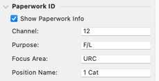
Attach Channel, Purpose, Focus Area, and Position Name data to the beam.
By default, channels are displayed on the beam object, with their text attributes being controlled via Vectorworks’s Text menu. You can use Settings... to change which data are displayed.
The Channel and Purpose will transfer to any Lighting Devices created with Beam Draw’s command. You can also use Beams with channels to create magic sheet layouts.
This data remains in sync with any linked Lighting Devices.
- Show Paperwork Info
Toggle whether to draw the below information with the beam.
- Channel
The channel number will show at the focus point if the beam is shown or at the instrument location if it is hidden. The channel can be used to create a BeamViz Magic sheet object.
- Purpose
The purpose will transfer when a beam is converted to a Spotlight lighting device.
- Focus Area
The Focus Area will append the Purpose, i.e., "Front US".
If Focus Area is blank or matches the selected Focus Point in the Focus section, this value will change if you select a new Spotlight Focus Point. If this value has manual data, BeamViz will not allow that data to change when you select a new Focus Point.
- Position Name
When you attach the light location to a Rigging Object, this field will synchronize to the Rigging Object's Position Name.
When you , the resulting Lighting Device will also attach to the position in the same place.
Classes
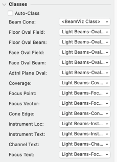
You can assign a class to most of the Beam’s geometry.
- Auto-Class
Select Auto-Class to create and assign classes to each possible component. BeamViz will only create new classes for component parts that are enabled to draw.
Unchecking will leave the classes assigned, but allow you to individually change the classes of each component, including setting to the overall object's class (<BeamViz Class>).
View Buttons

- View from Light
Looks from the light to the focus point, in perspective.
- Look at Light
Looks from the focus point to the light in perspective.
- View Section
Looks at the beam from the left, orthogonal to the light’s throw.
Link Buttons
Available when unlinked
- Link to Lighting Device
Searches for a Lighting Device near the Light point, and if found, will create a link between the Beam and the Lighting Device.
Available when linked

- Unlink
Removes the link between the Beam and Lighting Device. Both objects remain in the drawing, and no other data is affected.
- Select Linked
Selects the linked lighting device, changing the active layer if necessary.
- Ignore Location of Linked
When selected, the location of the Beam and Lighting Device remain independent, but Paperwork data synchronizes.
Useful for drawing vertical positions or lights offset for clarity when not using Schematic Views.
- Update
Updates the Beam with all data from the Lighting Device, overriding any data in conflict. This includes location, focus, and data.
Settings
The Settings button raises a dialog where you can set the default class and Move to Layer prefix for all new Beam objects.
There is also an option to set which interactive mode to use when duplicating beams. The following consolidated calculations (computed beam information) can be displayed in the OIP (object info Palette). This section includes calculated information about the beam at its specified focus:
Throw (True distance)
Pan
Tilt
Angle to Face
Width at Focus
Illuminance (Footcandles)

