If you haven’t already, download the Savvy Section Installer from the JBLD downloads page.
Make sure Vectorworks is not running. Run the Savvy Section Installer. Select your version of Vectorworks. The installer will install a folder called “-JBLD Source-4 Section” in your user Plug-Ins folder, containing the Savvy Section plug-in object and a file of component parts.
The Macintosh installer allows you to select a custom location for your Plug-Ins folder. Windows users with a custom user data location or Mac users having trouble with the installer can download the “Raw installer” and manually drag the “-JBLD Source-4 Section” folder to Plug-Ins. For more information, see this FAQ.
You may also email software(at)BenghiatLighting.com.
Getting Started
To use the Savvy Section object, you must either add it to your Workspace or locate the “Red Symbol”
Adding to your Workspace
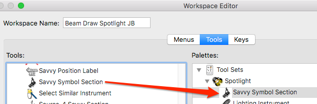
To add Savvy Section to an existing workspace:
Select Tools>Workspaces>Workspace Editor.
Select the Tools tab.
Click the disclosure triangle next to JBLD in the list of Tools categories on the left hand side.
Drag all the Source-4 Savvy Section Plug-Ins Objects to an existing palette on the right or create a new palette.
Click OK.
Adding to your Symbol Library
Open either your template file or one of your symbol libraries.
Go to the Resource Browser and select Browse a document.
Navigate to your Users Plug-In folder, and find the folder called “-JBLD Source-4 Section.”
Open the file called Section Parts.
Locate the red colored symbol called “~ Section>S/4.”
Import or place the symbol in your file. As soon as you place a “red symbol” in your drawing, it immediately converts to a plug-in object.
Registration
The first time you use the Savvy Section, you will be asked for a registration number. You can also access the registration dialog through the “About” button in the Object Info palette. The Savvy Section will not draw without a valid code.
Overview
The Source Four Savvy Section allows you to draw detailed 2D sections at any hanging angle, with any clamp, or barrel type, and add scrollers, top hats, and half hats.
The Savvy Section is a Plug-In Object, meaning you can draw any configuration with a single object using user-definable parameters. You can edit an object’s parameters in the Object Info Palette.
In Detail
Object Info Parameters
As with all Plug-In Objects, the first time you place a Savvy Section in a document, Vectorworks will ask you for default parameters. You can set the default object parameters for the document by selecting the object’s tool, then clicking on the parameters button in the mode bar.
Parameter
Description
x, y
The insertion point is the center of the pipe or sidearm.
Type
Source Four or Source Four PAR, in a side view or front view.
NOTE: Front views round to the nearest 45° and the angled versions only show the standard barrel and scroller size.
Rotation
You can rotate the entire object about its insertion point, but you may find this method more confusing than the Yoke and Body Angle parameters.
Yoke Angle
The angle, in degrees, of the yoke. 0 is straight down.
Body Angle
The angle, in degrees, that the body is focused. 0 is straight down. The angle is always measured with respect to the floor and is independent of the Yoke Angle.
In front view, the angle is rounded to the nearest 45 degrees. Use a negative angle to flip the light upside down (ie. flip the gel clip, etc.).
Clamp Type
C-Clamp, Tee, Coupler, or None; in front or side views.
Short-Yoke
Shows the body in the upper set of yoke holes. Note: PARS cannot be short yoked.
Show Pipe
Will show a standard 1.5″ pipe in the center of the C-Clamp.
Barrel Type
Switch between Standard, 90-deg, 70-deg, 14-deg, 10-deg, and 5-deg barrel types.
Scroller
Check to draw a scroller.
Scroller Size
Choose from 4″, 7.5″, 10″, and 15″ scrollers.
Note: You must decide which size scroller is appropriate.
Also Note: The front angled views currently only show one scroller size.
Top Hat
Check to add a top hat.
Top Hat Type
Choose from Full, Half, Full Short, and Half Short types.
Hat Size
Choose from 6 1/4″, 7 1/2″, 10″, 12″, and 14″ sizes.
Note: You must decide which size top hat is appropriate.
Color Extender
Check to add a color extender.
Flip
Flips the fixture horizontally (across the Y plane).
Settings…
Enters a dialog for setting Source Four Savvy Section preferences. Please note, these are system wide preferences, not drawing preferences.
Section Class Prefix – Select a class for the section object and its elements. Default: Symbols-Section. Please note, in order to change classes of the section symbol parts, you must edit the Section Parts document and manually rename the classes.
Symbol Folder – Select a symbol folder into which the section part symbols will be imported. Changing this preference will only affect future imported symbols and will not reorganize parts symbols in the current drawing. Default: ~Section Parts
Parts File Folder in Plug-Ins – You can select where the Source Four Savvy Section looks for the parts symbols. It must be a folder in your user Plug-Ins directory. Changing this setting allows you to use an alternate set of parts symbols or to share parts with another Savvy Section object.
About
Opens the about dialog, where you can enter your registration number, check the current version, and follow help links.
Changing Default Parameters
To change the default parameters for all new documents, choose Tools>Scripts>VectorScript Plug-in Editor…, select Source-4 Savvy Section, click the Parameters button, and edit the default values. Please note, if you install an update the object, you will have to redo these custom settings.
Using Classes to Control Detail
The Savvy Section’s components are divided into three classes:
Symbols-Section
Symbols-Section-Large Detail
Symbols-Section-Detail
You can take advantage of the classing in two ways. Firstly, you can hide or gray either of the detail levels to show varying levels of detail. Secondly, all objects have their attributes set by class. This means you can edit the default attributes for these classes, and the look of the Savvy Sections will adjust accordingly.
Editing Section Parts
Further customization of the Savvy Section is possible by editing the Section Parts Vectorworks file. You can edit any of the component parts in this file to your liking, including shape, attributes, and class. The only things you should NOT CHANGE are the size and insertion points of the component symbols, or the section parts will not assemble properly.
If you haven’t already, download the Savvy Symbol Key Installer from the JBLD downloads page.
Make sure Vectorworks is not running. Run the Savvy Symbol Key Installer. Select your version of Vectorworks. The installer will install a folder called “-JBLD Savvy Symbol Key” in your user Plug-Ins folder, containing the Savvy Symbol Key plug-in object and the Instrument Maintenance menu command.
The Macintosh installer allows you to select a custom location for your Plug-Ins folder. Windows users with a custom user data location or Mac users having trouble with the installer can download the “Raw installer” and manually drag the “-JBLD Savvy Symbol Key” folder to Plug-Ins. For more information, see this FAQ.
You may also email software(at)BenghiatLighting.com.
Getting Started
To use the Savvy Symbol Key object, you must add it to your Workspace.
Adding to your Workspace
To add Savvy Symbol Key to an existing workspace:
Select Tools>Workspaces>Workspace Editor.
In the Menus tab, click the disclosure triangle next to JBLD in the list of Menu categories on the left hand side.
Drag Instrument Maintenance to an existing menu on the right or create a new menu.
Select the Tools tab.
Click the disclosure triangle next to JBLD in the list of Tools categories on the left hand side.
Drag the Savvy Symbol Key Plug-In Object to an existing palette on the right or create a new palette.
Click OK.
Registration
The first time you use the Savvy Symbol Key, you will be asked for a registration number or demo code. You can also access the registration dialog through the “About” button in the Object Info palette. The Savvy Symbol Key will not draw without a valid code.
Overview
The Savvy Symbol Key is a plug-in object key to instrumentation. You can select and order your symbols for the key, as well as set several text and alignment attributes, and show unit type counts.
Spacing for extra wide symbols (like strip lights) or extra large symbols (like a 5K fresnel) is automatically adjusted.
Counts can be subtotaled to count bodies vs lenses. Symbols which have the same Instrument Type are counted together, allowing for alternate versions of a single type. Multi-circuit devices are counted properly.
There is also an Instrument Maintenance menu command to allow you to easily view and edit the Light Info Record, whose data appears in the key.
Click on the Savvy Symbol Key Tool icon, and then click on your drawing to insert. Because the object is scale independent, you may insert the object in a design layer, on a sheet layer, or in an annotation.
Build Symbol List
Click the Build Symbol List button in the Savvy Symbol Key’s Object Info palette. You will see a dialog with a list of symbols used as Lighting Devices in your drawing. You can click the top of the columns to sort by symbol name or by device type.
Move items you wuish to use in your key to the right column. You can select multiple symbols to add at once, or double click a symbol in either column to move it.
If you wish to add a symbol that you have not yet used as a Lighting Device, select Add Unused. Your chosen symbol will be added to your symbol key list. Unused symols that are already in your key list are shown in blue.
Use the Up, Down, and Sort buttons to arrange the order of your symbols. You can also drag the “-” on the left-hand side to reorder. You can select multiple symbols to move at a time.
You can also break down a symbol to its component parts. For example, if you have a symbol containing both a douser and a barn door, you can break this down in to two symbols for your key. Each symbol must have its own Light Info Record.
If you would like to subtotal bodies , insert a marker where you would like to begin and end the subtotal. You can insert as many pairs as you wish.
If you want your key to be multiple columns, add a column break. You can insert as many as you wish. You can also add horizontal dividers and header text. After you’ve added it, double-click on header text to edit.
To add a “Typical” symbol, add the Typical marker in your symbol list and select a symbol to use.
Multi-Circuit Devices
The best way to insert multi-circuit lights in your key is to use a master symbol which contains all the component parts. If you are using Vectorworks 2011, a symbol containing only other symbols is automatically converted into a multi-circuit device. You can also design a separate symbol for the key, for example, a shortened version with a break line in the middle. The Savvy Symbol Key shifts the symbol and its text to elegantly fit your key.
Make sure your composite symbol appears on the Instrument Maintenance list. If not make sure to add it. Standard practice is to indicate the wattage for each circuit, not the net wattage of the entire instrument.
Select your Savvy Symbol Key and enter the Build List dialog.
Click Add Unused and select your compound symbol. Place it in your key list.
Select the multi-circuit symbol and press # Circuits. Enter the number of circuits for that symbol, and the count will be correct.
Note: For multi-circuit units to count properly, the types and wattages of all the circuit components as well as the symbol in your key must match. You can check this in Instrument Maintenance and push that data out to your Lighting Devices.
Adjust Display Parameters
Use the Object Info Palette to adjust the visual spacing and scale of your key. Use the Text menu to set any font attributes other than size. You can also add a border and title to the key. See the next section for an explanation of the object’s parameters.
Instrument Maintenance
The Savvy Symbol Key uses the Light Info record for its data. The Light Info record contains real-world data about a lighting instrument and is attached to all Spotlight symbols which can be used as Lighting Devices. Instrument Maintenance allows you to easily edit all the Light Info records in your drawing in one dialog.
Select the Instrument Maintenance menu item.
You will see a dialog listing all the symbols in your document with the Light Info Record attached, which means they have the necessary data to use as Lighting Device Objects.
Click on a symbols Type, Wattage, Weight, or Model Name to edit. The Model Name field will be used in your symbol key, while the Type field appears in the Lighting Device data, and subsequently, your paperwork.
Adding a backslash ( ) anywhere in a text field will force a line break in the symbol key.
After you have changed a data item, be sure to press Update.
You can easily add a new symbol to the list, remove a symbol, or replace the units of a certain type with another symbol.
When you exit the dialog, pressing Done, you have the option of updating all your existing Spotlight Lighting Devices with any updated fields. You can select Push all data to Lighting Devices to apply the Instrument Maintenance data to all Lighting Devices regardless of whether they have been updated.
In Detail
Counting
The Savvy Symbol Key counts all Lighting Devices whose Type and Wattage match those in the symbol’s Light Info Record. This allows you to have alternate version of an instrument type (for example, overhung / underhung, regular / shortened, etc) and still have them counted as a single type in the key.
For multi-circuit units to count properly, the types and wattages of all the circuit sections as well as the composite symbol must match. You can check this in Instrument Maintenance and push that data out to your Lighting Devices.
Object Info Parameters
As with all Plug-In Objects, the first time you place a Savvy Symbol Key in a document, Vectorworks will ask you for default parameters. You can set the default object parameters for the document by selecting the object’s tool, then clicking on the parameters button in the mode bar.
Parameter
Description
x, y
The insertion point is the insertion point of the top instrument on your list.
Column Offset
The distance, on center, between columns. In page units. see fig 1
Item spacing
The vertical distance between instruments. The object will add additional distance if a symbol is larger than the unit spacing. In page units. see fig 1
Auto Rotate
If selected (default) symbols will be rotated in the orientation that minimises vertical distance.
Left margin
The maximum distance to the left of the insertion point for symbols to extend. If a symbol exceeds the margin, it will be slid to the right. In page units. see fig 1
Text distance
The distance between the insertion point and the text origin. In page units. see fig 1
Text width
The maximum width of text before it wraps. In page units. see fig 1
Text size
In points. Other text attributes are set though the Text menu.
Scale
The scale for your symbols, as a proportion. If this number is not familiar, see the Layer Scale dialog.
Show Wattages
Append “@ [wattage]” to an instrument’s type. Note, a blank wattage or a wattage of 0 will not show in the key.
Show Weights
Display the unit’s weight, as set in the Light Info Record. If your drawing uses metric units, the key will display the weight set in Light Info Record M.
Show Lamp Types
Display the unit’s lamp information, as set in the Light Info Record. Note, this is the lamps spec or ANSI code, as distinct from the wattage. You may include the wattage here in lieu of the wattage field.
Show Counts
Select to show instrument counts.
Show Column Headers
Will display the headers “Symbol,” “Description,” and “Count” above their respective columns. The text size depends on the Title Text Size.
Heading Alignment
When you add a header to the list, it can align to the left or center.
Draw Border
Select to draw a border around the symbol key. The border will use the object’s attributes.
Border Type
Choose between single and double lines.
Border Separation
The separation between double lines.
Border Padding
The distance, in page units, between the bounding box of the symbol key and the border.
Draw Title
Draws a title for the symbol key box. You need not draw a border to display the title. Border Padding affects the title even is the border is not drawn.
Title
The text of the title, e.g. “Symbol Key.”
Title Text Size
The size of the title text
Title Text Position
Above the border, Inside the border’s double lines or on the single line, Below the top of the border.
Show Data
Shows your symbol lists as text arrays.
Refresh
Redraws the object, which is useful if you have changed a symbol’s geometry or database.
Build List
Use the resulting dialog to select and sort the symbols you with to use for your key.
Position Filter
For future use.
Make Default
Will use the object’s current setting for future new Key Symbols.
About…
Check the version, enter registration information, and get help.
fig 1
Changing Default Parameters
To change the default parameters for all new documents, choose Tools>Scripts>VectorScript Plug-in Editor…, select Savvy Symbol Key, click the Parameters button, and edit the default values. Please note, if you install an update the object, you will have to redo these custom settings.
If you haven’t already, download the Beam Draw Installer from the JBLD downloads page.
Make sure Vectorworks is not running. Run the Beam Draw Installer. Select your version of Vectorworks. The installer will install a folder called “-JBLD Beam Draw” in your user Plug-Ins folder, containing the Beam Draw plug-in objects and menus.
The Macintosh installer allows you to select a custom location for your Plug-Ins folder. Windows users with a custom user data location or Mac users having trouble with the installer can download the “Raw installer” and manually drag the “-JBLD Beam Draw” folder to Plug-Ins. For more information, see this FAQ.
You may also email software(at)BenghiatLighting.com.
Getting Started
When the installation completes, start VectorWorks and select Tools>Workspaces>Beam Draw Standard or Tools>Workspaces>Beam Draw Spotlight. The Beam Draw workspace is similar to the VectorWorks Standard and SpotLight workspaces, but with a Beam Draw palette containing the Beam Draw Tools, and a Beam Draw menu. Use the About Beam Draw… menu item or the About… button in Object Info to enter your Beam Draw registration or demo code.
Adding to an Existing Workspace
To add Beam Draw to an existing workspace:
Select Tools>Workspaces>Workspace Editor.
In the Menus tab, click the disclosure triangle next to Beam Draw in the list of Menu categories on the left hand side.
Drag all the commands to an existing menu on the right or create a new menu.
Select the Tools tab.
Click the disclosure triangle next to Beam Draw in the list of Tools categories on the left hand side.
Drag the all the Beam Draw Plug-In Objects to an existing palette on the right or create a new palette.
If you want to use the Beam Draw tool set icon, you can find it installed in your user workspaces folder.
Click OK.
Registration
The first time you use the Beam Draw, you will be asked for a registration number or demo code. You can also access the registration dialog through the “About” button in the Object Info palette or the About Beam Draw… menu item.. The Beam Draw objects will not draw without a valid code.
Overview
Beam Draw allows you to visualize a beam of light in both plan view and 3D, helping you to choose proper instrument type and location. The beam instantly redraws if you change its beam angle, focus position, or instrument position.
The following diagram shows some of the terminology used by Beam Draw:
Beam Draw utilizes Plug-In Objects, meaning it draws beams according to a set of user-definable parameters, including beam angle, position height, and face plane. You will find a full list of parameters described for each object. You can edit an object’s parameters in the Object Info Palette.
As with all Plug-In Objects, the first time you place a beam in a document, VectorWorks will ask you for default parameters. You can set the default object parameters for the document by selecting the object’s tool, then clicking on the parameters button in the mode bar.
The fill Beam Draw package includes several plug-in objects and menus. Please visit the Beam Draw Quickguide page for a brief introduction to each Beam Draw component.
Workflow
Here is a sample workflow for using Beam Draw to visualise a system of lights. Please see the Quickguide as well as the detailed descriptions of each component to determine how to best incorporate Beam Draw into your design process.
Insert in the Drawing
Click on the Beam Draw Tool icon .
Click on the drawing in the approximate plan location where you would like the light to hang.
Drag the beam edge or focus point (indicated by a locus) to the point you would stand when focusing the light. The size and shape of the beam will change accordingly.
Alternatively, you can insert the beam at its focus point and drag the boxed control point to a hanging position. Your cursor will change to a double arrow when it is over the control point.
You can also use nudge (shift+arrow) to fine tune the focus point.
Adjusting Parameters
Many aspects of the beam are controllable though parameters in the Object Info Palette.
You’ll want to make sure your beam is being calculated from the correct height with the Position Height parameter. Use Distance to Clamp to drop (positive distance) or raise (negative distance) the origin of the beam below the position to its focal point. If you have lighting positions with z height values, press the Pickup Z Height button at the bottom of Obj Info.
Towards the bottom of the parameters is an option to Show Floor, showing the beam at both the face and floor planes.
You can set the Field and Beam angles towards the top of the parameters. Use a Beam angle of 0 to work only with the field angle. You can also press the Get Light Info Data button to access the beam and field angles and candlepower stored in the Light Info Record of your symbols. The symbols that shipped with Spotlight as well as those commercially available, like Soft Symbols, have photometric data already attached to them. Use the Use Light Info for Selected menu command to apply Light Info data to more than one beam object.
To visualize shutter cuts, make sure Show Shutter Cuts is checked. You can drag shutters via a control point right in the drawing or enter a depth and rotation in Obj Info.
Viewing the Beam in 3D
Switch to a 3D view. The beam will continue to reshape if moved in 3D.
You may want to hold down the shift key while moving the beam in 3D so its focus height does not change.
Reverse and Repeat
You can easily reverse and repeat beams across the x=0 centerline. Shutter cuts and bottle rotations are also reversed. Note: do not use the mirror tool with Beam objects, or they will draw unpredictably.
Select the beam objects you want to reverse and repeat. They can be any mix of Beam Draws and Beam Draw Pars.
Select the menu Reverse and Repeat Beams.
Creating a Consistent System of Lights
Use Beam Draw or Beam Draw PAR to select the proper position, beam angle, and focus of one light. You may find it useful to have a paper section in front of you, or to examine the beam in a 3D side view. Hint: Beam Draw also computes the distance and angle to the face.
Now change the Redraw parameter from Dynamic to Fixed.
You can now duplicate, duplicate array, or option/alt-drag the beam, and the instrument location will move, keeping the shape of the beam constant.
Channeling Beams
If you’re working with a single system of beams, you may find it useful to assign channel numbers.
If no beams are selected, the command channels all beams on the current layer. Otherwise the command works with selected beams of any type.
Choose the menu Channel Beams.
You will see a dialog allowing you to select the first channel and the direction channels will number.
The channel displays at the focus point. You can change the font and size using the Text menu.
Select a beam, and at the bottom make sure Show Paperwork Info is checked. You can manually set channel and purpose here. Those fields can automatically transfer when a beam is turned into a Spotlight Lighting Device.
Uncheck the Show Beam parameter and select Display Field Angle. The beam object reduces to the focus point (if it’s shown) and the instrument location, with the channel, field angle, and direction displayed. This is useful for creating a rough plot from your beans.
Converting Beams to Spotlight Lighting Devices
Select the Beam Draw and or Beam Draw PAR objects you wish to convert. If no beams are selected, the command converts all beams on the current layer.
A dialog will ask you to match each field angle with a symbol in your document. There is also a set of symbols whose field angles are close to your selected beam.
Choose if you want the symbols aligned to the drawing grid and rotated to the neatest 90°.
For now, do not delete beam objects after they are converted.
Any channel and purpose data entered into your Beam Draw objects will be transferred to your Lighting Devices.
Move Beams to a Layer
Select the beams you wish to file on another layer. If no beams are selected, the command converts all beams on the current layer.
Select the Move Beams to Layer menu.
You will be prompted for a suffix name for the layer, usually the system name. The layer name can be new or existing.
The beams are moved. New layers are hidden by default.
Making a Magic Sheet
If you channeled your beams, you can easily lay out a magic sheet.
Switch to a sheet layer.
If you like, use viewports to create a cropped, miniature version of the set. Make sure the 0,0 point of your drawing is snappable in the viewport.
Select the Beam Draw Magic tool.
Click in the drawing at the 0,0 point of your magic sheet.
Use Object Info to pick a layer — all channeled beams will appear as numbers in the Magic object.
Set a scale in Obj Info (e.g. 1/8″=1′-0″ would be 96).
Set the font for the channel numbers via the text menu.
Use Object Info to provide an offset for all channels (e.g. numbers are +10) or show them reverse and repeated.
The Move by Points basic tool can be useful for duplicating your Magic object / viewport combination.
In Detail
Beam Draw
Overview
Beam Draw allows you to visualize the coverage of a beam of light in plan view. Each beam is a separate Plug-In Object with easily adjustable hanging and focus points. Beam Draw will reshape as you move the focus across the drawing, and it will even show hyperbolic and triangular intersection with the face plane. Beam Draw can also show how the same beam will hit the floor as well as show the beam in 3D views.
Instructions
Click on the Beam Draw Tool icon .
Click on the drawing in the approximate plan location where you would like the light to hang.
Drag the beam edge or focus point (indicated by a locus) to the point you would stand when focusing the light. The size and shape of the beam will change accordingly.
Alternatively, you can insert the beam at its focus point and drag the boxed control point to a hanging position. Your cursor will change to a double arrow when it is over the control point.
You can also use nudge (shift+arrow) to fine tune the focus point.
Adjust parameters of the beam in the Object Info palette.
If you are viewing shutter cuts, you can adjust the shutters in Object Info as well as by dragging the four control points in the drawing.
The Beam Draw parameters can be edited in the Object Info Palette. To set parameter defaults, see the Overview.
Parameter
Description
x, y
The coordinates of the focus point.
Z
The height from which trims are measured, usually 0. If you are measuring trims from a show deck or platform, enter that height here.
Rot
Rotation is handled by the script. Should always be 0.
Instrument X, Y
The coordinates of the lighting instrument.
Instrument Distance X, Y
The x and y distances from the focus point to the lighting instrument.
Position Height
The height of the lighting position.
Distance to Clamp
The distance from the hanging position to the source point in the lighting instrument. The height of the beam is computed as Position Height – Distance to Clamp.
Field Angle
The field angle of the beam.
Beam Angle
The beam angle of the beam. If you do not want to draw the beam angle, enter a value of 0. If you only want to draw the beam angle, enter it in field angle.
Peak Candela
The peak candela of the beam. This is optional and used for computing footcandles.
Show Beam
Show or hide the beam ovals. If hidden, an arrow at the instrument location will show which direction the beam focuses.
Display Field Angle
Select to show the field angle indicated next to the instrument location.
Show Focus Point
If checked, a locus is drawn at the focus point.
Indicate Inst. with
A box or locus at the instrument location.
Show Shutter Cuts
Select for the ability to specify shutter cuts. If you hide cuts, the shutter parameters will still be retained.
Shutter Depth
The percentage to push in a shutter. 100% is at the focus point. You can also use control points in the drawing to drag shutter cuts.
Shutter Rack
The angle of each shutter
Resolution
Select “Low” to see the outlines of the beam more clearly in 3D.
Resolution Factor
Set the resolution for the Low Resolution option. 360 is a fairly full resolution. 4 should be the minimum.
Face Plane
The height of the plane on which beams are drawn. Usually 6’0”
Show Floor
If checked, will draw the beam at both head height and as it falls on the floor.
Add Light
Adds a light object with the same parameters of the beam. The light will only show as a pool of light using RenderWorks rendering.
Redraw
In dynamic mode, the lighting instrument remains fixed and the beam reshapes as you move it. In Fixed mode, the lighting instrument will move as you drag the beam, keeping the shape constant. Fixed mode is useful for duplicating a beam into a system of lights.
True Distance
The actual distance between the instrument and focus point. Useful for finding the light’s intensity at the face. Do not edit this field as it is computed by the object script.
Angle to face
The angle from the face to the light. Straight top light is 90°.
Pan
The degrees from straight up on the page (US, North, etc)
Tilt
The degrees from straight down.
Maximum Width
The maximum width of the beam at head height.
Footcandles
The computed intensity of the light.
Show Paperwork Info
Shows options to indicate a channel and purpose to keep track of your beams.
Channel
The channel number will show at the focus point if the beam is shown or at the instrument location if it is hidden. The channel can be used to create a Beam Draw Magic sheet object. The channel will also transfer when a beam is converted to a SpotLight lighting device.
Purpose
The purpose will transfer when a beam is converted to a SpotLight lighting device.
Get Light Info Data
Brings a dialog where you can select beam and field data from the symbols in your document and the symbols in your default file. Beam Draw will display the footcandles each unit type will output at the current throw.
Reset Shutters
Pulls out all the shutters.
Pickup Z height
Will change the position height to the z height of any 3D object below the instrument location. This does not change dynamically and will happen when you press the button.
Beam Draw PAR
Overview
Beam Draw PAR functions just like Beam Draw, only it visualizes elliptical beams. You can set the bottle rotation to any angle.
Instructions
Click on the Beam Draw Tool icon .
Click on the drawing in the approximate plan location where you would like the light to hang.
Drag the beam edge or focus point (indicated by a locus) to the point you would stand when focusing the light. The size and shape of the beam will change accordingly.
Alternatively, you can insert the beam at its focus point and drag the boxed control point to a hanging position. Your cursor will change to a double arrow when it is over the control point.
You can also use nudge (shift+arrow) to fine tune the focus point.
Adjust parameters of the beam in the Object Info palette.
You can rotate the beam in Object Info or by dragging the control point in the drawing that is near the beam’s focus point.
Parameters
The Beam Draw PAR parameters can be edited in the Object Info Palette. To set parameter defaults, see the Overview.
Parameter
Description
See Beam Draw Parameters, with the following exceptions
Shutters
PAR Objects cannot show shutter cuts
Field Angle H
The horizontal field angle
Field Angle V
The vertical field angle
Beam Angle H
The horizontal beam angle
Beam Angle V
The vertical beam angle
Bottle Rotation
The angle of bottle rotation. The bottle can also be rotated via a control point in the drawing.
Get Light Info Data
Will show and return H & V field and beam angles.
Beam Draw Section
Overview
Beam Draw Section allows you to draw a 2D triangle of light showing an instrument’s spread in section. You can select beam and field angles for the beam, visualize shutter cuts. You can display a figure as well as identify an area with minimum coverage width.
In order to keep beams from extending infinitely, the Beam Draw Section has four display modes, selectable in object info:
Mode
Description
Control Points
The beam will terminate at the two draggable control points that also define shutter cuts. Shutter cut control points are available in the other modes, but they only affect the beam ends in this mode.
Horizontal
The beam ends will terminate on a line horizontal with the focus point.
Vertical
The beam ends will terminate on a line vertical with the focus point. This option is useful for visualizing illumination of drops or scenery.
Focus Area
The beam ends will terminate at the floor, as defined bu the face plane. In this mode, you also have the option to view a figure whose head is at your focus point.
Instructions
Click on the Beam Draw Section Tool icon .
Click and drag from the gate of your light to your focus point. If you would rather drag in the opposite direction, use the Beam Draw Section from FP Tool.
If you don’t have representations of lighting instruments in your section, you can end the line at the hanging position. Next, click the button labeled “Shift by clamp height,” and your beam will compensate.
Adjust the section’s options, including Field Angle in Object Info.
To visualize shutters, make sure “Draw Shutters” is selected in Object Info. You will see a control point handle towards the ends of the beam section. Drag the point, and the shutter cut will pass through the point. You cannot open the shutters wider than the field angle permits.
Parameters
Parameter
Description
x, y
The coordinates of the ogirin of your beam, the gate of your light.
z
If you want to use the 2D section in a 3D plane, this is the distance above the working plane.
Rotation
The angle from the light to the focus point.
Throw Distance
The distance from the light to your focus point.
Field Angle
The field angle of the beam.
Beam Angle
The beam angle of the beam. If you do not want to draw the beam angle, enter a value of 0. If you only want to draw the beam angle, enter it in Field Angle.
Peak Candela
The peak candela of the beam. This is optional and used for computing footcandles.
Display Options
Show Beam
Deselect to hide the beam edges. You will see a locus at the origin of your beam. If shown, your figure will stay visible.
Display Field Angle
Select to show the field angle indicated next to the beam origin.
Show Shutters
Select to show shutter cuts and the shutter cut control point handles. If you deselect, any shutter cuts you made will still be preserved.
Extend the beam a distance beyond the points defined in Beam Ends.
Focus Area Options (Available in Focus Area Beam End mode)
Face Plane
The height above the floor to which the beam focused.
Show Figure
Draws a 6′ figure at the focus point. You also have a control point handle at the figure’s feet.
Show area limits
Use this option to visualize coverage in the plane perpendicular to the section. For example, say you want to see coverage for an 8′ area. After setting Area Width to 8′, you will see a rectangular area that shows the limits of you 8′ area.
Area Width
The width of minimum coverage shown in Show Area Limits.
Origin Options
Show Clamp Position
Draws a locus at the instrument’s C-clamp.
Distance to clamp
The distance from the light’s gate to the hanging point of the C-clamp.
Shift by clamp height
Shifts the origin of the beam down to compensate for the distance between the C-clamp and the light’s origin at the gate. Useful if you are drawing the section between the hanging position and the focus point, rather than a sectioned view of the lighting instrument.
-Computed Info-
Throw Dist
The distance from the light to the focus point.
Angle to Face
The angle from the face to the light. Straight top light is 90°.
Footcandles
The computed intensity of the light.
Maximum Width
The maximum width of the beam at head height.
Reset Shutters
Press this button to completely open the shutter cuts. Useful if your shutters are all the way in to the center of the beam.
Get Light Info Data
Brings a dialog where you can select beam and field data from the symbols in your document and the symbols in your default file. Beam Draw will display the footcandles each unit type will output at the current throw.
Beam Draw Section from FP
Overview
This will insert the Beam Draw Section object, draw from the focus point to the hanging posiion.
Instructions
Click on the Beam Draw Section from FP Tool icon .
Click and drag from your desired focus point to your hanging position.
The resulting object is identical to that described in Beam Draw Section.
Use Light Info for Selected
Overview
This command will utilize data attached to your symbols to provide you with a library of beam angles, field angles, and peak candela to apply to your Beam Draw Objects. The data is extracted from the Light Info Record in your symbol definitions. Thee symbols that shipped with Spotlight as well as those commercially available, like Soft Symbols, have photometric data already attached to them.
Data will be shown for symbol definitions in your current document as well as those in your Spotlight Default content folder.
Instructions
Select any mix of Beam Draw, PAR, and Section objects.
Choose the Use Light Info for Selected menu command.
You will see any photometric data attached to the symbol resources in your drawing as well as those in the Spotlight Default content.
Beam draw computes the brightness, in footcandles, for the first selected Beam Draw object in your drawing.
Select a symbol whose data you want to use.
If you only want to use the field angle, click Ignore Beam Ang, otherwise, click OK.
Your beams will now use the data you selected.
Reverse and Repeat Beams
Overview
You can easily reverse and repeat beams across the x=0 centerline. Shutter cuts and bottle rotations are also reversed. Note: do not use the mirror tool with Beam objects, or they will draw unpredictably.
Instructions
Select the beam objects you want to reverse and repeat. They can be any mix of Beam Draws and Beam Draw Pars.
Select the menu Reverse and Repeat Beams.
Channel Beams
Overview
If you’re working with a single system of beams, you may find it useful to assign channel numbers. The channels can be shown on the drawing, transfer to Spotlight Lighting Devices when using the Convert Beams command, and be used for creating magic sheets.
Instructions
If no beams are selected, the command channels all beams on the current layer. Otherwise the command works with selected beams of any type.
Choose the menu Channel Beams.
You will see a dialog allowing you to select the first channel and the direction channels will number.
The channel displays at the focus point. You can change the font and size using the Text menu.
Select a beam, and at the bottom make sure Show Paperwork Info is checked. You can manually set channel and purpose here. Those fields can automatically transfer when a beam is turned into a Spotlight Lighting Device.
Uncheck the Show Beam parameter and select Display Field Angle. The beam object reduces to the focus point (if it’s shown) and the instrument location, with the channel, field angle, and direction displayed. This is useful for creating a rough plot from your beans.
Convert Beams to Instrument
Overview
This command allows you to insert Soptlight Lighting Devices or instrument symbols for each of the beams. You can easily match beam angles to unit types.
Instructions
Select the Beam Draw and or Beam Draw PAR objects you wish to convert. If no beams are selected, the command converts all beams on the current layer.
A dialog will ask you to match each field angle with a symbol in your document. There is also a set of symbols whose field angles are close to your selected beam.
Choose if you want the symbols aligned to the drawing grid and rotated to the neatest 90°.
Choose whether you want beams converted to Lighting Devices or just regular symbols.
You can opt to delete beams after they are converted, though most users save them for reference.
Any channel and purpose data entered into your Beam Draw objects will be transferred to your Lighting Devices.
Move Beams to Layer
Overview
Once you have created a system of beams, you can easily move them to a new layer and begin a new system.
Instructions
Select the beams you wish to file on another layer. If no beams are selected, the command converts all beams on the current layer.
Select the Move Beams to Layer menu.
You will be prompted for a suffix name for the layer, usually the system name. The layer name can be new or existing.
The beams are moved. New layers are hidden by default.
Select Beams
Overview
Use thie command to select all Beam Draw objects.
Select PAR Beams
Overview
Use thie command to select all Beam Draw PAR objects.
Select Section Beams
Overview
Use thie command to select all Beam Draw Section objects.
Select All Beams
Overview
Use thie command to select all Beam Draw object types, including PAR and Section.
About Beam Draw…
Overview
Provides information about the current Beam Draw version and registration. You can enter a purchased registration number or a requested demo code via this dialog. There are also a number of support links in the dialog.
Beam Draw FAQ
Overview
Go to the FAQ on the web.
Beam Draw Help
Overview
Open this help doc.
Submit a Beam Draw Bug
Overview
Submit a bug report on the web.
Changing Default Parameters
To change the default parameters for all new documents, choose Tools>Scripts>VectorScript Plug-in Editor…, select Beam Draw, click the Parameters button, and edit the default values. Please note, if you install an update the object, you will have to redo these custom settings.
If you haven’t already, download the Savvy Position Pipes Installer from the JBLD downloads page.
Make sure Vectorworks is not running. Run the Savvy Position Pipes Installer. Select your version of Vectorworks. The installer will install a folder called “-JBLD Position Pipes” in your user Plug-Ins folder, containing the Savvy Position Pipes plug-in objects and the Convert PP to LPO and Batch Label Positions menu commands.
The Windows installer allows you to select a custom location for your Plug-Ins folder. Mac users with a custom user data location or Windows users having trouble with the installer can download the “Raw installer” and manually drag the “-JBLD Position Pipes” folder to Plug-Ins. For more information, see this FAQ.
You may also email software(at)BenghiatLighting.com.
Getting Started
To use the Savvy Position Pipes object, you must add it to your Workspace.
Adding to your Workspace
To add Savvy Position Pipes to an existing workspace:
Select Tools>Workspaces>Workspace Editor.
In the Menus tab, click the disclosure triangle next to JBLD in the list of Menu categories on the left hand side.
Drag Batch Label Positions and Convert PP to LPO to an existing menu on the right or create a new menu.
Select the Tools tab.
Click the disclosure triangle next to JBLD in the list of Tools categories on the left hand side.
Drag the four Position Pipe Plug-In Objects to an existing palette on the right or create a new palette.
Click OK.
Registration
The first time you use Savvy Position Pipes, you will be asked for a registration number or demo code. You can also access the registration dialog through the “About” button in the Object Info palette. The Savvy Position Pipes will not draw without a valid code.
Overview
The Savvy Position Pipes is a package of plug-in objects for drawing lighting positions. Features include adding tick marks at regular intervals, single or double line drawing styles, both 2D and 3D components, and line weight consistency through classes.
There is also a useful command for labeling sequential positions and for converting the Position Pipe objects to Spotlight Light Positions.
Click on the Position Pipe Tool icon. Draw the pipe as you would a line, click-dragging or click-clicking on the two endpoints. You may want to be drawing with only snap-to-grid with a 3″ snap grid on in your constraints. While not required, finding a good snap grid for all your positions will help create a neat and accurate plot.
Position Pipe Arc
Click on the Position Pipe Arc Tool icon. The Mode Bar will show two drawing modes — Center-Line and Edge Placement. You will probably prefer drawing in edge placement mode. Draw the width, then depth of your arc. The object will fit itself inside the box you have drawn. You can also specify a specific radius in Object Info.
Position Pipe Ladder
Click on the Position Pipe Ladder Tool icon. This object also has two drawing modes. Draw the width, then height of your ladder.
Position Pipe Poly
Click on the Position Pipe Poly Tool icon. This click on the position’s vertices, just as you would while drawing an ordinary polygon.
Setting Hatch Marks
All the Position Pipe objects can show tick marks at regular intervals. All objects have the following parameters:
Center alignment
Whether the hatches start on center or evenly split center
Centers
The distance between hatch marks
Hatch Type
Select between a dot or a line
Size of Hatch
The length of the line or the radius of the dot
Length of Gap
To emphasize the tick mark, you can specify a gap between the hatch and the line of the pipe
Hatch Offset
If the ends of the pipe do not line up with the drawing grid, or if your pipe is not centered on the center-line, you can offset the hatch origin from the center of the pipe.
The linear position pipe has an Align Hatch to Grid button that will automatically adjust the hatch origin to match the horizontal grid.
Setting Pipe Style
Every Position Pipe object can draw as a single or double line. The Pipe Diameter parameter sets the separation between the double lines as well as the diameter of the pipes in 3D.
End Markers
For single line pipes you can show end markers at the beginning and ends of pipes. The length of the end markers matches the pipe diameter.
Footprints
In Top/Plan (2D) View, you can choose to show a 2D projection of the position in plan view. This can be useful if you are showing the poitsion offset or rotated for clarity, or if the position has a 3D rotation (for example, a pipe diagonal to the horizon).
To show a footprint, select the Show Footprint check box. You can now set the footprint offset and rotation. You can also drag the footprint by a control point that is at the left of the position.
3D Rotation
Each position can rotate in several axis. The 2D version of the pipe only rotates in the screen plane, always showing the full length of the pipe.
Axis
Description
Applies to
Rotation (K)
Rotates in the screen plane, parrallel to the ground.
All
I
Rotates around an axis perpendicular to the position. Poly pipes rotate around the insertion point. Arc and ladder pipes rotate around their centers.
Poly, Arc, Ladder
J
Rotates around an axis perpendicular to the position. Standard and poly pipes rotate around the insertion point. Arc and ladder pipes rotate around their centers.
All
Note:
Ladders assume a vertical orientation for their 3D view, so any rotation is from vertical.
Class Assignment
All Position Pipes are drawn in the same class. By default, this is “Hanging Position.” In order to change the class, either select an object and choose Settings… from Object Info, or select an object’s tool, click the preferences icon on the mode bar, and choose Settings… Select an existing class from the list or create a new class.
The class setting extends across all Position Pipe objects. Hatch marks are in the Hatch subclass. Footprints are in the Footprint subclass. Arc objects have loci at your specified spacing to facilitate unit insertion. The loci are in the Hatch-Locus subclass.
If you want your pipes to use a texture in 3D renderings, assign a texture to the Hanging Position class.
Converting to Spotlight Lighting Positions
If you would like to take advantage of Spotlight’s position related tools, you can easily convert your positions to Light Position objects. Select one or more Position Pipes. They can be a mix of standard, Arc, Poly, and Ladder pipes. Select the menu item Convert PP to LPO that you added to your workspace. If you have assigned a position name to your Position Pipe in Object Info, that name will transfer to the Spotlight Light Position.
The geometry for Light Positions is stored in a symbol. To edit the Position Pipe, look in the Resource Browser for the corresponding symbol and edit.
In Detail
Object Info Parameters
As with all Plug-In Objects, the first time you place a Savvy Position Pipe in a document, Vectorworks will ask you for default parameters. You can set the default object parameters for the document by selecting the object’s tool, then clicking on the parameters button in the mode bar.
Position Pipes
Parameter
Description
X, Y, Z
The position of the insertion point of your pipe (your first click).
Rotation
Rotation in the 2D screen plane, parallel to the ground plane, about the insertion point.
J Rot
Rotation about an axis perpendicular to the position, about the insertion point. A positive rotation will pivot the pipe up, away from the ground.
Pipe Length
The length of the pipe, as measured from the insertion point. You can enter a length here or drag the handles at the ends of the position.
Hatches
Determines if hatch marks will start from the center of the pipe or evenly split center.
Centers
How far apart to draw the hatch marks.
Hatch Type
Choose between a line or a filled dot.
Size of Hatch
The length of the hatch line or the radius of the hatch dot.
Length of Gap
To emphasize the hatch mark, you can specify a gap between a pipe’s single line representation and the hatch. This is in world units. For no gap, specify 0. This setting has no effect on double line pipes.
Hatch Offset
If the center of your pipe does not align with the space’s center-line, you can offset the hatch marks from the pipe’s geometric center. (See also, Align Hatch to Grid)
Line Type
Draw the pipe as a single or double line. The Pipe Diameter parameter sets the separation between the double lines.
Pipe Diameter
Sets the separation between double line pipes as well as the diameter of the pipe in 3D.
Draw Pipe
Uncheck to hide the representation of the pipe. Useful if you just want hatch marks visible, like for a row of overhung lights. Also useful to duplicate the hatch marks in a layer above the lights.
Draw Hatched
Uncheck to hide hatch marks.
End Marker
For single line pipes you can show end markers at the beginning and ends of pipes. The length of the end markers matches the pipe diameter. Options are None, Start, End, and Both. Double line pipes will have emphasis on the ends of the pipe regardless of this setting.
Show Footprint
In Top/Plan (2D) View, you can choose to show a 2D projection of the position in plan view. This can be useful if you are showing the position offset or rotated for clarity, or if the position has a 3D rotation (for example, a pipe diagonal to the horizon).
Footprint Origin
How far the footprint is offset from the pipe’s origin.
You can enter values here or drag the control point on the left of the pipe. As the footprint defaults to directly below the position, you may want to enter an offset manually in order to see the control point apart from the pipe.
Footprint Rotation
Select a rotation for the footprint about it’s origin.
Position Name
Enter a name for this position. If you convert the position to a Spotlight Light Position, the name will transfer. You can also set the name with the Batch Label Menu Command.
Align Hatch to Grid
Click this button to align the hatch marks to the closest horizontal reference grid point. Note: If you have selected a user defined origin, limitations in Vectorworks may prevent this feature from working correctly.
Settings…
In the resulting dialog, choose the base class for your positions.
About…
Check the version, enter registration information, and get help.
Position Pipe Arc
Parameter
Description
X, Y, Z
The position of the insertion point of your pipe (the center of your bounding box).
Rotation
Rotation in the 2D screen plane, parallel to the ground plane, about the insertion point.
I Rot
Rotation about an axis parallel to the position’s width, about the center.
J Rot
Rotation about an axis perpendicular to the position, about the center. A positive rotation will pivot the pipe up, away from the ground.
Arc Width
The width of the arc, as defined by its bounding box. You can enter a length here or drag the handles at the sides or corners of the position.
Arc Depth
The depth of the arc, as defined by its bounding box. You can enter a length here or drag the handles at the sides or corners of the position.
Radius
If you are fitting the arc in its bounding box, this will be calculated. If not, you can specify a radius here.
Calculate Radius from Box
If this option is selected, the arc’s radius will be defined as the arc passing through the top corners and bottom center of your bounding box. If unselected, the arc will draw from the radius parameter and be truncated by the sides of the bounding box.
Note: The maximum arc’s sweep is 180°.
Hatches
Determines if hatch marks will start from the center of the pipe or evenly split center.
Centers
How far apart to draw the hatch marks.
Hatch Type
Choose between a line or a filled dot.
Size of Hatch
The length of the hatch line or the radius of the hatch dot.
Length of Gap
To emphasize the hatch mark, you can specify a gap between a pipe’s single line representation and the hatch. This is in world units. For no gap, specify 0. This setting has no effect on double line pipes.
Hatch Offset
If the center of your pipe does not align with the space’s center-line, you can offset the hatch marks from the pipe’s geometric center.
Line Type
Draw the pipe as a single or double line. The Pipe Diameter parameter sets the separation between the double lines.
Pipe Diameter
Sets the separation between double line pipes as well as the diameter of the pipe in 3D.
Draw Pipe
Uncheck to hide the representation of the pipe. Useful if you just want hatch marks visible, like for a row of overhung lights. Also useful to duplicate the hatch marks in a layer above the lights.
Draw Hatched
Uncheck to hide hatch marks.
End Marker
For single line pipes you can show end markers at the beginning and ends of pipes. The length of the end markers matches the pipe diameter. Options are None, Start, End, and Both. Double line pipes will have emphasis on the ends of the pipe regardless of this setting.
Show Footprint
In Top/Plan (2D) View, you can choose to show a 2D projection of the position in plan view. This can be useful if you are showing the position offset or rotated for clarity, or if the position has a 3D rotation (for example, a pipe diagonal to the horizon).
Footprint Origin
How far the footprint is offset from the pipe’s origin.
You can enter values here or drag the control point on the left of the pipe. As the footprint defaults to directly below the position, you may want to enter an offset manually in order to see the control point apart from the pipe.
Footprint Rotation
Select a rotation for the footprint about it’s origin.
Position Name
Enter a name for this position. If you convert the position to a Spotlight Light Position, the name will transfer. You can also set the name with the Batch Label Menu Command.
Settings…
In the resulting dialog, choose the base class for your positions.
About…
Check the version, enter registration information, and get help.
Position Pipe Poly
Parameter
Description
X, Y, Z
The position of the insertion point of your pipe (your first click).
Rotation
Rotation in the 2D screen plane, parallel to the ground plane, about the insertion point.
I Rot
Rotation about an axis parallel to the position’s width, about the insertion point.
J Rot
Rotation about an axis perpendicular to the position, about the insertion point. A positive rotation will pivot the pipe up, away from the ground.
Total Pipe Length
The length measured along the pipe.
Hatches
Determines if hatch marks will start from the center of the pipe or evenly split center.
Centers
How far apart to draw the hatch marks.
Hatch Type
Choose between a line or a filled dot.
Size of Hatch
The length of the hatch line or the radius of the hatch dot.
Length of Gap
To emphasize the hatch mark, you can specify a gap between a pipe’s single line representation and the hatch. This is in world units. For no gap, specify 0. This setting has no effect on double line pipes.
Hatch Offset
If the center of your pipe does not align with the space’s center-line, you can offset the hatch marks from the pipe’s geometric center. (See also, Align Hatch to Grid)
Line Type
Draw the pipe as a single or double line. The Pipe Diameter parameter sets the separation between the double lines.
Pipe Diameter
Sets the separation between double line pipes as well as the diameter of the pipe in 3D.
Draw Pipe
Uncheck to hide the representation of the pipe. Useful if you just want hatch marks visible, like for a row of overhung lights. Also useful to duplicate the hatch marks in a layer above the lights.
Draw Hatched
Uncheck to hide hatch marks.
End Marker
For single line pipes you can show end markers at the beginning and ends of pipes. The length of the end markers matches the pipe diameter. Options are None, Start, End, and Both. Double line pipes will have emphasis on the ends of the pipe regardless of this setting.
Show Footprint
In Top/Plan (2D) View, you can choose to show a 2D projection of the position in plan view. This can be useful if you are showing the position offset or rotated for clarity, or if the position has a 3D rotation (for example, a pipe diagonal to the horizon).
Footprint Origin
How far the footprint is offset from the pipe’s origin.
You can enter values here or drag the control point on the left of the pipe. As the footprint defaults to directly below the position, you may want to enter an offset manually in order to see the control point apart from the pipe.
Footprint Rotation
Select a rotation for the footprint about it’s origin.
Position Name
Enter a name for this position. If you convert the position to a Spotlight Light Position, the name will transfer. You can also set the name with the Batch Label Menu Command.
Align Hatch to Grid
Click this button to align the hatch marks to the closest horizontal reference grid point. Note: If you have selected a user defined origin, limitations in Vectorworks may prevent this feature from working correctly.
Settings…
In the resulting dialog, choose the base class for your positions.
About…
Check the version, enter registration information, and get help.
Position Pipe Ladder
Parameter
Description
X, Y, Z
The position of the insertion point of your pipe (your first click). The z values determines the height of the ladder’s bottom pipe.
Rotation
Rotation in the 2D screen plane, parallel to the ground plane, about the insertion point.
I Rot
Rotation about an axis parallel to the position’s width, about the center point.
J Rot
Rotation about an axis perpendicular to the position, about the center point. A positive rotation will pivot the pipe up, away from the ground.
Ladder Width
The ladder’s horizontal width.
Ladder Height
The ladder’s vertical length.
Number of Rungs
The number of the ladder’s rungs, including the top and bottom.
Guides
Determines how the ladder’s pipes draw in relation to the width and height.
Center – the pipes are centered around the rectangle determined by the ladder’s width and height.
Outside – the inside edge of the outer pipes align to the ladder’s rectangle.
Inside – the outside edge of the outer pipes align to the ladder’s rectangle.
Hatched
Determines if hatch marks will start from the center of the pipe or evenly split center.
Centers
How far apart to draw the hatch marks.
Hatch Type
Choose between a line or a filled dot.
Size of Hatch
The length of the hatch line or the radius of the hatch dot.
Length of Gap
To emphasize the hatch mark, you can specify a gap between a pipe’s single line representation and the hatch. This is in world units. For no gap, specify 0. This setting has no effect on double line pipes.
Hatch Offset
If the center of your pipe does not align with the space’s center-line, you can offset the hatch marks from the pipe’s geometric center. (See also, Align Hatch to Grid)
Line Type
Draw the pipe as a single or double line. The Pipe Diameter parameter sets the separation between the double lines.
Pipe Diameter
Sets the separation between double line pipes as well as the diameter of the pipe in 3D.
Draw Pipe
Uncheck to hide the representation of the pipe. Useful if you just want hatch marks visible, like for a row of overhung lights. Also useful to duplicate the hatch marks in a layer above the lights.
Draw Hatches
Uncheck to hide hatch marks.
Show Footprint
In Top/Plan (2D) View, you can choose to show a 2D projection of the position in plan view. Because the ladder’s 2D view is a front view, the footprint will be a top view of the ladder.
Footprint Origin
How far the footprint is offset from the pipe’s origin.
You can enter values here or drag the control point on the left of the pipe. As the footprint defaults to directly below the position, you may want to enter an offset manually in order to see the control point apart from the pipe.
Footprint Rotation
Select a rotation for the footprint about it’s origin.
Position Name
Enter a name for this position. If you convert the position to a Spotlight Light Position, the name will transfer. You can also set the name with the Batch Label Menu Command.
Irregular Rung Spacing
Click this button to enter a custom spacing between ladder rungs. Normally, the ladder rungs are evenly spaced.
Settings…
In the resulting dialog, choose the base class for your positions.
About…
Check the version, enter registration information, and get help.
Changing Default Parameters
To change the default parameters for all new documents, choose Tools>Scripts>VectorScript Plug-in Editor…, select Savvy Position Pipes, click the Parameters button, and edit the default values. Please note, if you install an update the object, you will have to redo these custom settings.
Savvy Linesets is a complete solution for managing lineset drafting and documentaion
One centralized worksheet of data, that you can edit, paste in data from a spreadsheet application, or build from clicking in the plan.
Highly configurable, industry standard lineset schedules and hanging plots.
Simplified batten references.
Flattened lineset sections that you can use to build and refine your hanging items.
Create pipes and masking with a single menu command, even the 3D component, and keep them all perfectly in sync with your data.
No more discrepancies, or time spent manually rippling changes.
Requirements
Vectorworks® Spotlight 2015–2017
Installation
If you haven’t already, download the Savvy Linesets Installer from the JBLD downloads page.
The installer package must remain a zip file. If your system automatically unzips archives, right-click on the download link and select “Save Link As” to prevent your browser from auto-expanding the download.
In Vectorworks, select Tools > Plug-ins > Plug-in Manager
Select the Third-party plug-ins tab
Click the Install… button
Navigate to and select the saved installer zip file
Read and confirm the EULA
Vectorworks should notify you that installation is complete and to restart Vectorworks
If you experience trouble with the install script, please see the following FAQ on where plug-ins install.
The installer includes a workspace called Spotlight+Linesets. You can also use the workspace editor to add the lineset commands to your own workspace.
You may also email software(at)BenghiatLighting.com.
Getting Started
When the installation completes, start Vectorworks and select Tools>Workspaces>Spotlight+Linesets
Adding to an existing Workspace
To add the Savvy Linesets to an existing workspace:
Select Tools>Workspaces>Edit Current Workspace.
Click the disclosure triangle next to JBLD in the list of Menus categories on the left hand side.
You may want to create a new menu or submenu to display Savvy Linesets.
Drag all the Savvy Linesets menu commands one by one to the menu tree on the right side.
Select the Tools tab.
Click the disclosure triangle next to JBLD in the list of Tools categories on the left hand side.
Drag Savvy LS Sched, Fill LS Sched From Clicks, and Savvy LS Section to an existing palette on the right or create a new palette.
Click OK.
Registration
The first time you use the Savvy Linesets, Vectorworks will ask you for a registration number or demo code. You can also access the registration dialog through the “About” button in any object’s Object Info palette. The Savvy Linesets objects will not draw without a valid code, however if you remove the Savvy Linesets plug-ins from your user folder, you will still see all lineset objects but in a locked state.
Overview
Savvy Linesets stores all lineset schedule data in a centralized worksheet. Savvy Linesets Schedule objects display a formatted schedule in the drawing and Savvy Linesets Sections create a flattened 2D section based directly on your data.
In addition, you can synchronize battens, electrics, and softgoods to the schedule data so your drawing model, and you can even create these objects directly from schedule data.
Take a full video tour via YouTube
The Lineset Worksheet
Overview
The Lineset Worksheet is a Vectorworks worksheet resource that stores all data describing the lineset configuration. Any time you use one of the Savvy Linesets tools or commands, Savvy Linesets will automatically create the worksheet.
Savvy Linesets Settings allows you to set the name used for this worksheet.
You can use the Fill LS Sched from Clicks tool to add Number and Distance data in the worksheet by clicking on existing lineset reference points in the drawing. You can also copy and paste date from a spreadsheet application or manually edit the worksheet.
You can edit the header cell of any column, and that text will appear on Schedule objects placed in the drawing. Columns must remain in the given order.
In addition to accessing the Worksheet through the resource browser, Savvy Linesets objects provide a button to open the Worksheet, and you can also double-click on the Savvy Linesets Schedule Object.
Worksheet columns
Columns below designated with an * do not appear in schedule objects.
Number A label for each lineset. Usually this is a number from DS to US, but can be any text, for example “1 Bridge,” “Fire,” or “Spot Line.”
To refer to the lineset by distance, for example when working in a hemp house, enter a hyphen (-) in the Number column.
To add an additional row that does not appear on the schedule, use a decimal point. For example, LS 6 might have a softgood and 6.1 has a truss. This allows both the truss and softgood objects to sync to the schedule data. You can also use this method to display an alternate trim.
In addition to appearing on the schedule, this helps identify objects int he drawing that synchronize to lineset data. The number appears in the Location field for Lighting Pipes, Light Position Objects, and Softgoods.
Dist. Distance from plaster / setting line
Description A brief description of the item. In addition to appearing on the schedule, this synchronizes to the Position Name field for Lighting Pipes and Light Position Objects and to the Note field for Softgoods.
Trim The trim height of the item. This corresponds to the z height of objects in the drawing. Via Savvy Linesets Settings, you can opt to trim Softgoods to the bottom of the softgood (default) or to the batten.
Length The length of the batten. This length can synchronize to the length of Lighting Pipes, Truss, or Lines representing battens, including if they are converted to Light Position Objects.
Setting a batten length also create a reference to pipe ends using the Lineset Schedule object in Mini/Double mode.
Depth The US/DS depth of the item. The depth can set the height of the schedule’s cells for Style 2 as well as optional depth indicators on the schedule’s extension lines.
Weight A column to report the lineset’s weight. This is a text column that you manually enter.
Note An additional note about the item
LX?* Enter a “y” to designate this item as an electric. Electrics have options to be called out in the schedule. You can also chose to draw pipes or truss for all items designated as electrics and to convert them to Light Position Objects.
Sft Gd?* Enter a “y” to designate this item as a softgood. Softgoods rows will draw in section and can also create Softgood objects.
Item Height* For softgoods, this corresponds to the hight of the softgood. Also use this setting to designate a trim measurement that offsets from the batten. For example, a practical that trims to the bottom of the fixture. A positive value sets the trim point below the batten.
Item Width* Softgoods must set a length here. Other objects can use this column to override the Length column, for example a tail down that is shorter than the system pipe.
Plug-in objects
As with all Plug-In Objects, the first time you place a Savvy Linesets object in a document, Vectorworks will ask you for default parameters. You can set the default object parameters for the document by selecting the object’s tool, then clicking on the parameters button in the mode bar.
Savvy Lineset Schedule Object
Overview
Use this object to represent the schedule in the drawing.
Select the Savvy LS Sched tool: . Insert at the plaster / setting line. The schedule can rotate to accommodate a section as well as flip orientations when mirrored.
Use the Mini option to create simplified indictions of the linesets. Use the Double option of the Mini mode to indicate the ends of battens based on the Distance and Length data. Insert the Double Mini at Centerline / Plasterline.
Double-click on the Schedule to quickly access the lineset data worksheet.
Parameters
Parameter
Description
Format
Mini LS Schedule
Enable to draw the lineset numbers only. Useful for showing pipe ends or as a simple reference.
Mini Type
Single displays the numbers in a single column, while double will show numbers at the pipe ends. In Double mode, only rows with a pipe length will display.
Show 3D Loci
When enabled, the Mini format will show 3D locus points at pipe ends rather then the planar schedule.
Display Style
Select a display style. Format 1 shows a single box. Format 2 draws a box around each row that has an item label.
Expand
Reserved for future use.
Min Item Box Height
For Format 2, this sets a minimum height for a row, in world units.
Max Item Box Height
For Format 2, this sets a maximum height for a row, in world units.
Leader Length
The length of the line between the schedule body and the lineset number, in page units.
Columns
Column Order
Click to set the order for data columns.
Flip Columns
Revers the column order. This can be useful when flipping or mirroring the schedule.
Header Position
Place column headers at the top or bottom of the schedule. Note, headers draw from the columnslabels, in the Lineset Workshet. Edit the worksheet to change the header text.
Column Widths
Label Width
Width of the Label column, in page units.
Note Width
Width of the Note column, in page units.
Trim Width
Width of the Trim column, in page units.
Distance Width
Width of the Distance column, in page units.
Weight Width
Width of the Weight column, in page units.
Pipe Length Width
Width of the Pipe Length column, in page units.
Column Visibilities
xx Column
Select which data columns are visible.
Text Options
Text Size
Size of the schedule text, in points.
Font
Font of the schedule text
LX Font
Font of text for rows designated as electrics
LX Font Size Multiplier
Value by which to multiply the text size for rows designated as electrics.
Padding
Padding between text and the schedule’s lines, in page units.
Extensions
Show Extensions
Show lines extending from the schedule for each lineset, on the opposite sise of the lineset number.
Flip Extensions
Enable to draw the extensions on the same side as the lineset number.
Extension Length
The length of the extension lines, in world units.
Show Depth indicators
Add a vertical line at the end of the extension corresponding to the Depth column in the schedule worksheet.
LX Markers
Add an arrow marker to the extnension line. Filled circles or diamonds are a common choice.
LX Marker style
Set the type of markers to display for electrics.
Classes
Auto-Class
Enable to automatically generate sub-classes based on the class designated in Settings.
Schedule
Class for the schedule text and lines.
Schedule-LX
Class for rows designated as electrics
Update
Refresh the schedule based on worksheet data.
Update Objects from Schedule
Update Lighting Pipes, Truss, Softgoods, Light Position Objects, and Savvy LS Items based on the worksheet data. There is an identical menu command.
Update Schedule from Objects
Update the schedule worksheet with data from Lighting Pipes, Truss, Softgoods, Light Position Objects, and Savvy LS Items in the drawing. There is an identical menu command.
Display Lineset Worksheet
Click to display the Lineset Worksheet. You can also double-click on the schedule object in the drawing.
Make default
Click to make the settings for this Scheudule object the default for all new Schedules in this drawing.
Settings…
Set preferences for all Savvy Lineset objects in the drawing. There is an identical msnu command.
About…
Informaiton about this version and your user registration.
Savvy Lineset Item Object
Overview
Drawing objects that are not Lighting Pipes, Straight Truss, Light Position Objects, or Softgoods can be made “Savvy Lineset Aware” by converting to a Savvy Lineset Item via the associated menu command.
Both 2D and 3D geometry becomes embedded in the Lineset Item. You can edit the geometry at any time via Modify>Edit Savvy LS Item or by double-clicking on the object.
Edits to the object’s parameters and z location immediately ripple through to the Worksheet and Section. Changes to the Section immediately update the Item Object. If you make changes directly to the schedule Worksheet, however, you must either press the Update button or run the Update Objects from LS Sch command.
Parameters
Parameter
Description
LS Number
The lineset on which the object hangs. You can use this menu to assign the item to a different lineset. Linesets marked with a star (*) are in use.
Label
A description of the item.
Electric
Check to designate this object as an electric.
Edit
Click to edit the items geometry.
Update
Refresh the object with any changes in the Schedule Worksheet.
About…
Informaiton about this version and your user registration.
Savvy Lineset Section Object
Overview
Creates a 2D section of the linesets and hanging items. The Lineset Section generates directly from the schedule Worksheet.
Select the Savvy LS Section Icon: . You can insert the Section Object in any orientation to match your overall section. A Flip button in Object Info allows you to flip the orientation of the schedule after insertion.
You may want to insert a Savvy Linesets Section object above the Section object as well as use the Schedule object in Mini mode to provide a lift line reference.
Changes to the Section automatically update Schedule objects and the Worksheet. If you make changes directly to the Worksheet, use the Update button in Object Info or the Refresh menu command to refresh the Section.
If your workflow is predominantly 3D, use the Savvy Lineset Section over a flattened section viewport of the model.
Parameters
Parameter
Description
Grid Height
Designate the top of lift lines
Max Out Trim
Designate the height for gridded pipes without a trim.
Classes
Auto-Class
Enable to automatically generate sub-classes based on the class designated in Settings.
Section
Class for the overall section.
Lift Line
Class for the lift lines.
Update
Refresh the section based on worksheet data.
Update Objects from Sched
Update Lighting Pipes, Truss, Softgoods, Light Position Objects, and Savvy LS Items based on the worksheet data. There is an identical menu command.
Update Sched from Objects
Update the schedule worksheet with data from Lighting Pipes, Truss, Softgoods, Light Position Objects, and Savvy LS Items in the drawing. There is an identical menu command.
Flip
Flip the direction of the section with respect to the insertion point.
Display Lineset Worksheet
Click to display the Lineset Worksheet. You can also double-click on the schedule object in the drawing.
Settings…
Set preferences for all Savvy Lineset objects in the drawing. There is an identical msnu command.
Make Default
Click to make the settings for this Section object the default for all new Sections in this drawing.
About…
Informaiton about this version and your user registration.
Savvy Lineset Section Item Object
Overview
Each lineset has a Section Item Object that you can individually select, configure, and move.
The Savvy Lineset Schedule manages insertion and removal of Section Items. Do not manually insert or paste Savvy Linesets Section Item Objects.
In addition to the parameter in object info, drag, nudge, or use the move command to set an Item’s trim.
Designating the Item as a softgood will draw a line representing the drape.
You can add additional geometry to the Section Item, like a lighting instrument, drape, scenic element, or practical. Edit the geometry via Modify>Edit Savvy LS Section Item or by double-clicking on the object.
Parameters
Parameter
Description
LS Number
The lineset on which the object hangs. You can use this menu to assign the item to a different lineset. Linesets marked with a star are in use.
Label
A description of the item.
Distance
Distance from plaster or setting line.
If Distance changes
Not used
Trim
The item’s trim. In addition to a dimension, the field recognizes the keywords in, out, and grid.
Electric
Check to designate this object as an electric.
Softgood
Check to designate this object as a softgood. Softgoods will draw a line indicating the softgood in section and synchronize paremeters with Softgoods objects.
SoftGoodClass
Designate a class for the line indicating the softgood in section.
Item Height
For softgoods, this corresponds to the hight of the softgood. Also use this setting to designate a trim measurement that offsets from the batten. For example, a practical that trims to the botttom. A positave value sets the trim point below the batten.
Symbol
Specify a symbol for the item. You can also edit the object and draw or insert any geometry. By default, this is a section of a pipe.
Draw Lift Line
Draw the lift line between the item and the grid.
Classes
Auto-Class
Enable to automatically generate sub-classes based on the class designated in Settings.
Item
Class for the item geometry.
Update
Refresh the section based on worksheet data.
Update Objects from Sched
Update Lighting Pipes, Truss, Softgoods, Light Position Objects, and Savvy LS Items based on the worksheet data. There is an identical menu command.
Update Sched from Objects
Update the schedule worksheet with data from Lighting Pipes, Truss, Softgoods, Light Position Objects, and Savvy LS Items in the drawing. There is an identical menu command.
Flip
Flip the direction of the section with respect to the insertion point.
Display Lineset Worksheet
Click to display the Lineset Worksheet. You can also double-click on the schedule object in the drawing.
Settings…
Set preferences for all Savvy Lineset objects in the drawing. There is an identical msnu command.
Make Default
Click to make the settings for this Section object the default for all new Sections in this drawing.
About…
Informaiton about this version and your user registration.
Tools
Fill LS Sched from Clicks
Use this tool to fill Number and Distance data in the lineset Worksheet.
The tool has two modes. The first mode assumes that the drawing origin is your plaster or setting line. In this mode, your first click will be on lineset 1. The second mode lets your first click designate the zero point for distance measurements.
Click in the drawing for each lineset location in sequence. The tool only reads the y location to set data in the Distance column. The Mode Bar help text indicates the linset number awaiting your click. Double-click on the last lineset position to complete the tool.
If the Worksheet already has data, the tool will confirm that you want to replace data in the existing worksheet.
Menu Commands
Refresh LS Scheds and Secs
Refresh the Schedule and Section objects based on any changes you made to the Worksheet.
Create objects from LS Shed
Use the schedule Worksheet to create Lighting Pipes, Straight Truss, Lighting Position Objects, and Softgoods corresponding to the schedule. The command will search for and update any existing objects that correspond to the schedule, and only create objects that don’t match.
First choose whether to create objects for all linesets, only linesets with an Item Description, or only Softgoods and/or Electrics.
Find existing objects via lineset number, distance, or unique item name.
The zero reference point can be the drawing origin or the next click.
Designate the type of object to draw for each empty pipe, softgood, or electric. Electrics may immediately convert to Light Position Objects, or remain the specified object in order to edit further.
Upon exiting the dialog, you will have the opportunity to set defaults for any object types new to the drawing.
Update Objects from LS Sch
Update Lighting Pipes, Straight Truss, Lighting Position Objects, Softgoods, and Savvy Lineset Items based on the schedule Worksheet. This command also updates objects when changes to the Savvy Lineset Section have updated the schedule Worksheet.
Choose to match objects via lineset number, distance, or unique item name. Use of these options can also help associate objects with the worksheet that weren’t created with the Create Objects from LS Sched command.
See The Lineset Worksheet for information on what data synchronize to objects.
For convenience, Schedule, Section, and Section Items have a button that preforms this menu’s function.
Update LS Sch from Objects
Update the schedule Worksheet from Lighting Pipes, Straight Truss, Lighting Position Objects, and Softgoods objects in the drawing. Lineset Schedules and Sections will also refresh to reflect the updated worksheet.
Choose to match objects via lineset number, distance, or unique item name. Use of these options can also help associate objects with the worksheet that weren’t created with the Create Objects from LS Sched command.
If an item’s y position differed from the value in the worksheet you will be prompted with options to correct the object’s position, change the distance in the worksheet, reassign to another lineset, or ignore.
See The Lineset Worksheet for information on what data synchronize to objects.
For convenience, Schedule, Section, and Section Items have a button that preforms this menu’s function.
Make Savvy Lineset Aware
Embed the selected objects in a Savvy Lineset Item object. Lighting Pipes, Straight Truss, Lighting Position Objects, and Softgoods sync directly to the schedule, so do not need this command to work with Savvy Linesets.
The dialog prompts you to pick a reference point on the selected object that aligns with the distance datum of the lineset.
You can immediately assign the Item to a lineset, though you can also leave this field blank and associate the object later via Object Info. If the lineset to which you assign the object is already in use, you will be prompted whether to use the existing name and trim.
Savvy Lineset Settings
Change settings that affect all Savvy Linesets objects
Lineset base class Specify a base class to use for all auto-classing.
Object Insertion Classes Specify default insertion classes for Lineset related objects. You can also choose to insert objects using the active class.
Lineset prefix Specify a prefix for identifying linesets. This appears in pull-down menus and in location fields for Lighting Positions and Softgoods. This is “LS” by default, and would normally not change, unless you want to indicate Truss, etc.
Trim Soft Goods from Specify how soft good trims measure, either bottom of the soft good or the batten.
Maximum out trim Set the maximum out trim for the Create Objects command and for the Lineset Section object. Changing this setting will not affect any existing objects.
Lineset Worksheet Name Specify a name for the Lineset Schedule Worksheet in the Resource Browser. This only changes the name Savvy Linesets uses to identify the data worksheet. If you wish to change the name of an existing worksheet, you must also do so in the Resource Browser.
Make default Make these settings default for all new drawings.
FAQ
Can I add columns to the Worksheet?
You can only add columns to the right of the worksheet, starting with Column M. However, only the six columns configurable in the Schedule object appear in the drawing: Number, Distance, Label, Note, Weight, and Item width.
Can I change the name of Schedule columns?
Yes, you can rename columns anything you wish. The names are reflected in the Lineset Schedule object.
What if the setting line is at the top of the drawing?
You can order linesets any way you wish in the Worksheet. Linesets DS of the setting line will have a negative distance.
How do I create Softgoods that are legs?
In order to use a single Softgoods object as legs, you essentially configure the object as an open traveller without a track. Set the Open From parameter to Center and the opening Width parameter to the space between legs.
What if an item object’s center does not align to the centerline of the stage?
Savvy Linesets creates new objects centered at x = 0. Once the object exists, you may move it left or right as needed. The object’s length will update if you change it in the schedule Worksheet, but the object’s left/right position will not change.
Can I place the Lineset Schedule on a sheet layer?
You can place a Schedule object in the Annotations of a Sheet Layer Viewport.
I’ve edited the symbol designated in Savvy Linesets Section Items. The lift lines don’t seem to be drawing to the correct point.
Currently, exiting a symbol definition can’t trigger Savvy Linesets Section Items to recalculate their bounding boxes. If this happens, select the Section Items with updated symbols and click the Update button.
If you haven’t already, download the Savvy Section Installer from the JBLD downloads page.
The installer package must remain a zip file. If your system automatically unzips archives, right-click on the download link and select “Save Link As” to prevent your browser from auto-expanding the download.
In Vectorworks, select Tools > Plug-ins > Plug-in Manager
Select the Third-party plug-ins tab
Click the Install… button
Navigate to and select the saved installer zip file
Read and confirm the EULA
Vectorworks should notify you that installation is complete and to restart Vectorworks
If you experience trouble with the install script, please see the following FAQ on where plug-ins install.
You may also email software(at)BenghiatLighting.com.
Getting Started
To use the Savvy Section object, you must either add it to your Workspace. Note, that if you are upgrading from the Source Four Savvy Section, this is a completely seperate tool to add to your Workspace.
Adding to your Workspace
To add Savvy Section to an existing workspace:
Select Tools>Workspaces>Workspace Editor.
Select the Tools tab.
Click the disclosure triangle next to JBLD in the list of Tools categories on the left hand side.
Drag all the Savvy Symbol Section Plug-Ins Objects to an existing palette on the right or create a new palette.
Click OK.
Registration
The first time you use the Savvy Section, you will be asked for a registration number. You can also access the registration dialog through the “About” button in the Object Info palette. The Savvy Section will not draw without a valid code.
Overview
The Savvy Symbol Section allows you to draw detailed 2D sections at any hanging angle, with any clamp, or barrel type, and add scrollers, top hats, and half hats.
The Savvy Section is a Plug-In Object, meaning you can draw any configuration with a single object using user-definable parameters. You can edit an object’s parameters in the Object Info Palette.
Insert in the Drawing
Select the Savvy Symbol Section icon from the tool set to which you added it. Insert in the drawing like a symbol.
Alternatively, you can create red symbols or object styles and add pre-configured secitons from your resource browser.
In Detail
Object Info Parameters
As with all Plug-In Objects, the first time you place a Savvy Section in a document, Vectorworks will ask you for default parameters. You can set the default object parameters for the document by selecting the object’s tool, then clicking on the parameters button in the mode bar.
Parameter
Description
X,Y
The insertion point is the center of the pipe or sidearm.
Style
The Savvy Symbol Section supports object styles. Use this menu to apply, create, or modify a Style definition for the Section. Section styles appear as “red” symbols in the Resource Manager, and specifies whether parameters reference the style definition. For more information, see Concept: Plug-in Object Styles in Vectorworks help.
Hide Style Parameters
Enable this option to hide any parameters linked to a style definition.
Symbol
Inst. Type
Choose from a catalog of instrument types. You can select form the following:
Selected symbol – By default, you can also choose any 2D or 3D symbol to use as the basis of the Section object.
Source Four
Source Four Mini
Source Four PAR
Source Four Fresnel
Source Four Lustr
Desire D20
Desire D40
Desire D60
Barrel
If you have a catalog symbol selected, you may also specify a barrel type. You can select from the following:
The name of the specified symbol. Useful to copy and paste a non-catalog symbol.
Warning
Feedback after selecting an invalid section symbol displays here
Symbol component
For user-defined symbols, select whether using the 2D component or a flattened 3D section.
Add fill
To save rendering time, a flattened 3D symbol displays as an unfilled hidden line render. Once you have configured the symbol, enable this option to add a solid fill.
Rotations
Standard View:
Select from a menu of standard view options. For flattened 3D symbols, you can also specify any plan rotation.
The following options are available:
Side <
45 < (A 45 degree box boom-type angle)
Front
45 >
Side >
Custom
NOTE: Front views round to the nearest 45°
Plan Rotation
The imagined plan rotation of the instrument you are viewing on section. As with the Top/Plan view, 0 is facing into the page and 180 faces away from the page, the “Front” view. Choosing a Standard View automatically enters this angle.
Yoke Angle
Specify an angle to “yoke” the unit forward or back from vertical. Note, this currently only displays the unit correctly in 2D side views or some 3D views. 0 is straight down. Enter 180 to top yoke the unit.
Body Angle
The tilt angle of the body from straight down.
In front view, the angle is rounded to the nearest 45 degrees. Use a negative angle to flip the light upside down (ie. flip the gel clip, etc.).
Flip
Press this button to flip the view left to right (e.g. change from a front light to a back light)
3D Components
Show Clamp/Base
Render the 3D part tagged as the “Base.” Unselect to use one of the 2D symbol options
Plan Rotate Clamp/Base
If you show the base, choose its plan orientation. Useful for showing the orientation of a moving light base.
Show yoke
Render the 3D part tagged as the “Yoke.” Unselect for the Savvy Section to draw its own yoke.
Draw clearance circle
Draw a clearance circle around the instrument, including accessories. For catalog instruments, this is based on a known radius. Otherwise, this is a best guess from the symbol’s geometry.
Clearance circle class
Specify a class for the Clearance Circle. By default, this uses the same class as the Savvy Section object instance.
Clamp
Type
Select from the following types of clamps and views:
C Clamp-Side
C CLamp-Front
Tee-Side
Tee-Front
Coupler-Side
Coupler-Front
Mini Clamp-Side
Mini Clamp-Front
Floor Plate
None
Number
Display multiple clamps, for example when hanging a moving light.
Separation
If showing multiple clamps, the distance between them
Show Pipe
Enable to show a 2″ pipe in section
Yoke
Draw Yoke
Enable for the Savvy Section to create the yoke for the section. Works in any view. Enabled by default for catalog symbols.
Yoke Length
The distance from the bottom of the clamp to the pivot point. Automatically entered for catalog and flattened 3D symbols.
Yoke Width
The inside width of the yoke. Useful for non-side views. This value also affects the placement of the Handle in non-side views.
Short-Yoke
Show the section in a short-yoke position.
Yoke Handle
Draw a yoke-tilt handle or bolts. You may select from the following:
Clutch (Default)
Standard
Bolt
None
Scroller
Scroller
Enable to draw a scroller. Scrollers in views other than side (any tilt) or front with a 90-degree tilt may take a couple seconds to calculate their geometry.
Scroller Size
Choose from a selection of scroller sizes. Choosing a catalog symbol will automatically select the most logical size.
CXI
Select this option to select a double scroller, like the CXI, which is typically fatter.
Accessory
Accessory
Enable this option to draw the selected accessory in front of the lens or scroller.
Accessory Type
Choose from the following:
Top Hat Full
Top Hat Half (a.k.a. Eyelash)
Top Hat Full Short (Half depth)
Top Hat Half Short
Barn Door
Gel frame
Accessory Size
Choose from a selection of accessory sizes. Choosing a catalog symbol or barrel will automatically select the frame size. You can also specify a custom frame size. Note, some scrollers take a different accessory size than the adaptor plate they use. Please consult manufacturer specifications for to confirm accessory sizes for use with scrollers.
Custom Size
Enter a value if you have selected the Custom size. Some catalog units, like Source Four Minis or Desires will enter the appropriate custom size here.
Half hat position
If you have selected a Half Hat, select how that Hat should orient in the unit.
Color Extender
In addition to the accessory, display a color extender.
Adjust V
If the accessory slot does not align with the center of the unit’s tilt point, this value will adjust the accessory up or down.
Adjust H
Use this value to adjust the accessory (and scroller) away from or towards the lens.
Settings…
Set preferences for the Savvy Symbol Section
Default insertion class: Choose a class for new Section objects. You can also opt to insert labels in the active class.
Component class prefix: All catalog symbols use three classes to separate the main section, large details, and small details. Enter a base class name for building these three classes. Any symbol components imported by the Savvy Symbol Section will adapt to this base class.
Symbol Folder: Select a folder for importing needed Section resources. The Savvy Symbol Section will maintain s few sub-folders within this folder.
Make default for all new documents: Select this option for these settings to be default values for all future new Vectorworks documents.
About…
See version and registration information
Using Classes to Control Detail
The Savvy Section’s components are divided into three classes:
Symbols-Section
Symbols-Section-Large Detail
Symbols-Section-Detail
You can take advantage of the classing in two ways. Firstly, you can hide or gray either of the detail levels to show varying levels of detail. Secondly, all objects have their attributes set by class. This means you can edit the default attributes for these classes, and the look of the Savvy Sections will adjust accordingly.
Editing Section Parts
Further customization of the Savvy Section is possible by editing the Section Parts Vectorworks file. You can edit any of the component parts in this file to your liking, including shape, attributes, and class. The only things you should NOT CHANGE are the size and insertion points of the component symbols, or the section parts will not assemble properly.
Using Your Own Symbols
Savvy Symbol Section provides an option to make any symbol into a Savvy Section. You have two options for working with non-catalog symbols:
2D Symbols
Specify any 2D symbol for use with Savvy Symbol Section. This can be a symbol used for a Lighting Device (like a Fresnel or PAR that may work well in plan or section) you a section you have drawn according to manufacturer specifications.
For side sections, orient the 2D symbol as you would to prepare it for use with lighting devices, pointing towards the top of the page, with the insertion point at the tilt pivot point. The bottom of the unit should face the left of the page. At this point, the symbol is ready to be savvy, though you may want to attach the data record described below for improved accuracy.
All front and angled view symbols are un-rotated (they should appear how they will in the section), with the insertion point at the pan / tilt pivot point.
3D Symbols
Any Spotlight-ready symbol should work with the Savvy Symbol Section. Please see the Spotlight Help section on assigning parts to 3D symbols.
Attaching the Savvy Section Info record
User-defined symbols should have the Savvy Section Info record attached. The record contains the following data:
YOKE LENGTH: distance from the top of the yoke to the pivot point
YOKE WIDTH: the width of the yoke, from center to center
SLOT OFFSET: the distance from the tilt axis to the center of the front accessory slot.
SLOT ADJUST V: If the lens is not at the midpoint of the tilt axis, enter an offset
ACCESSORY SIZE: Frame size
CLEARANCE RADIUS: The radius of the clearance for the instrument.
2D VIEW: Plan rotation.
HAS BARREL: Enable if this instrument has a barrel symbol
CUSTOM YOKE: If this symbol uses its own yoke symbol, enter the name here (with out the suffix -side, -front, etc.)
NOTES:
If a value is not needed, set to zero.
To accommodate units, these are text fields. You can use any units, but you must include units.
Examples: 12.5”, 218mm, 7cm, 1’2.5”
Click in the drawing to insert, either at the focus point or instrument location. You can drag both the beam (via its geometry) and the instrument location (via its control point). Numerous parameters are available in the Object Info palette, including showing shutter cuts. The bottom of Object Info will relay calculated information about the beam.
Beam Draw PAR
Click in the drawing to insert, similar to Beam Draw. You can spin the bottle right in the drawing via a control point.
Beam Draw Section
Click and drag from the light source (e.g. the unit’s gate) to the focus position. You can compensate for the clamp/yoke height or add a figure in Object Info.
Beam Draw Section from FP
Click and drag from the focus point to the light source. This will place a Beam Draw Section object in the drawing.
Beam Draw Magic
Click in the drawing at the 0,0 point of your magic sheet. Use Object Info to pick a layer — all channeled beams will appear as numbers in the Magic object. Set a scale in Obj Info (e.g. 1/8″=1′-0″ would be 96). Set the font for the channel numbers via the text menu. Use object info to provide an offset for all channels (e.g. numbers are +10) or show them reverse and repeated. Perfect for laying over a viewport of the set.
Menus
Use Light Info for Selected
You can select photometric data from a symbol’s Light Info record to apply to your selected beam object(s). You will see all symbols in your current document as well as in your SpotLight defaults file. There is an option to use only the field angles.
Reverse and Repeat Beams
Reverse and repeats selected beams accross x=0 (centerline). Sutter cuts and bottle rotations are also mirrored.
Channel Beams
Add channel numbers to selected beams. If no beams are selected, the command channels all beams on the current layer. Channel numbers appear at the focus point if the beam is visible or at the instrument location if it is hidden. Channeled beams can easily lay in to your magic sheet with the Beam Draw Magic Object. When you use the Convert Beams to Instrument command, channels will transfer to SpotLight lighting devices.
Convert Beams to Instrument
Converts selected beams to either symbols or SpotLight Lighting Devices. If no beams are selected, the command converts all beams on the current layer. You will be prompted to match an instrument symbol to each field angle. Beam Draw will siggest matches for you. If you are converting beams to a symbol, you can map channel and purpose data fields via the parameter defaults in the VectorScript Plug-In Editor.
Move Beams to Layer
Moves all Beam Draw objects to the layer of your choosing. You need only enter a system name, and Beam Draw will prefix the layer, and add it if it doesn’t exist. A new layer will be hidden by default.
Select Beams
Selects all Beam Draw Objects.
Select PAR Beams
Selects all Beam Draw PAR Objects.
Select Section Beams
Selects all Beam Draw Section Objects.
Select All Beams
Selects all Beam Draw regular, PAR, and Section Objects.
About Beam Draw…
Use this dialog to enter your serial number or demo code. You can also check the installed version.
Beam Draw FAQ
Links to the online FAQ.
Beam Draw Help…
Opens the PDF manual.
Submit a Beam Draw Bug
Go to the online bug submit form.
2025 News:
All plug-in solutions are now fully compatible with Vectorworks 2025! Dismiss
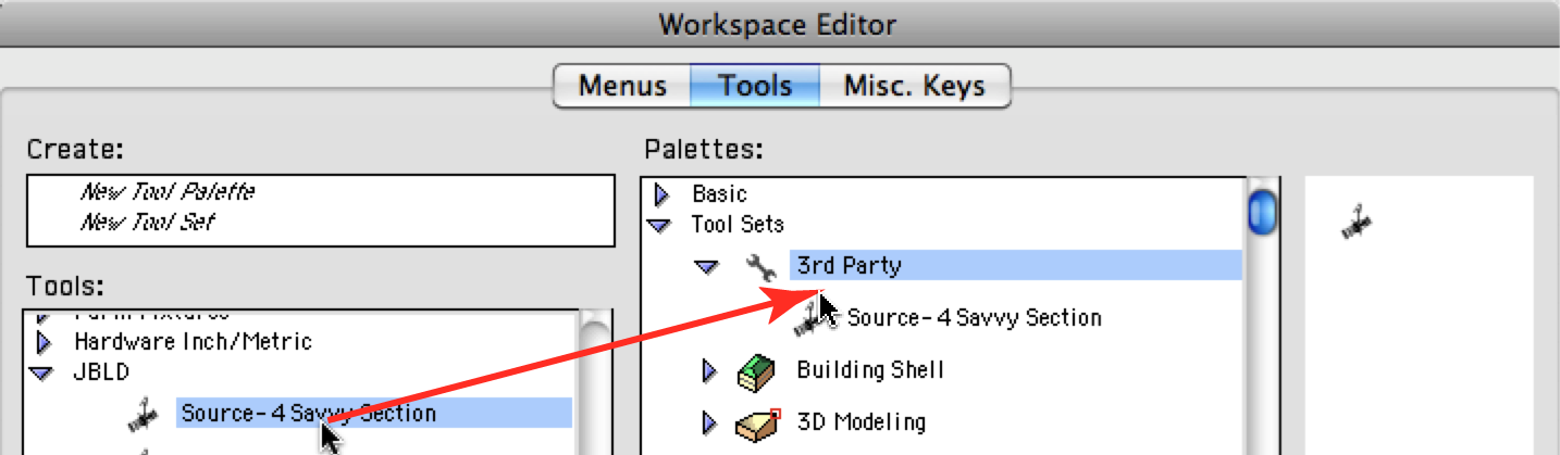


 The channel displays at the focus point. You can change the font and size using the Text menu.


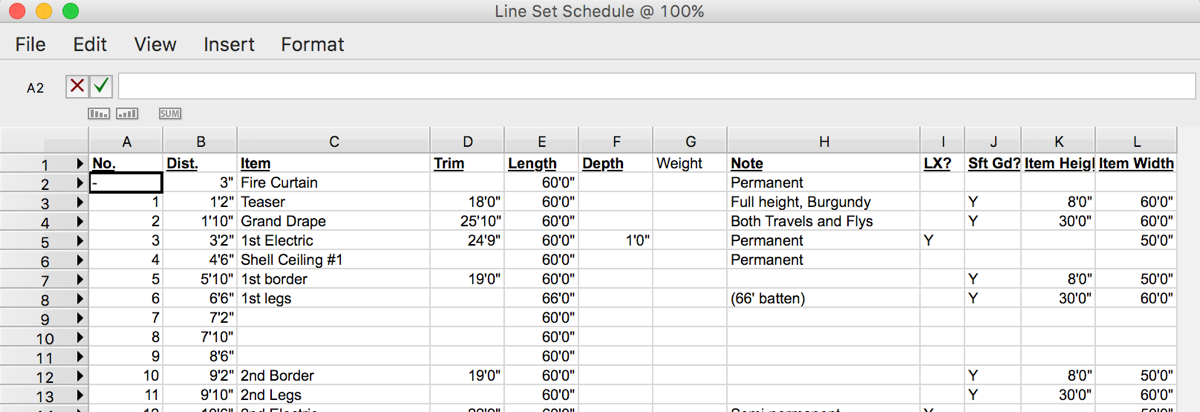

 in the mode bar.


 assumes that the drawing origin is your plaster or setting line. In this mode, your first click will be on lineset 1. The second mode
  lets your first click designate the zero point for distance measurements.