Savvy Position Label
version 2.0.0
User Guide
Created by Joshua Benghiat
Joshua Benghiat Lighting Design
Introduction
Requirements | Installation | Support
Getting Started
Adding to your Workspace | Registration | Overview
In Detail
– Placing in the Drawing
– Linking to a Position
– Object Parameters
– Known Issues
Frequently Asked Questions
Introduction
The Savvy Position Label is a plug-in object for labeling lighting positions and providing automatically updated notes about the position.
Savvy Configuration
Choose from numerous configuration options, allowing the Label to confirm to your personal drafting standard. The Savvy Position Label supports text styles and classes for granular control of its presentation.

Savvy Placement
The label is a separate object from the Lighting Position Object, so you can nudge or duplicate independently from the position. You can, optionally, have the label move with the position.
Savvy Label Text
Because you don’t always display the same position name on the plot that you use in the paperwork, the Savvy Position Label lets you display the first word, last word, just number, or custom text, with a prefix or suffix. Pipe A displays as A. #2 Electric becomes 2E, etc, while still automatically linking to the position name.
Savvy Note
An optional note lets you add tokens to automatically display US DS and SL SR coordinates, location, trim height, pipe length, and weight, which always stay up to date.

Requirements
Vectorworks® Spotlight 2018
Installation
If you haven’t already, download the Savvy Position Label from the JBLD downloads page.
-
The installer will have a .vwlibrary file extension for use with the Plug-in Manager. Do not manually install this file
-
In Vectorworks, select Tools > Plug-ins > Plug-in Manager
-
Select the Third-party plug-ins tab
-
Click the Install… button
-
Navigate to and select the saved installer file
-
Read and confirm the EULA
-
Vectorworks should notify you that installation is complete and to restart Vectorworks
If you experience trouble with the install script, please see the following FAQ on where plug-ins install. In the Plug-in Manager, you will see Savvy Position Label in the Built-in Plug-ins section.
Support
Please visit http://BenghiatLighting.com/software/support for support options and to report bugs.
You may also email software(at)BenghiatLighting.com.
Getting Started
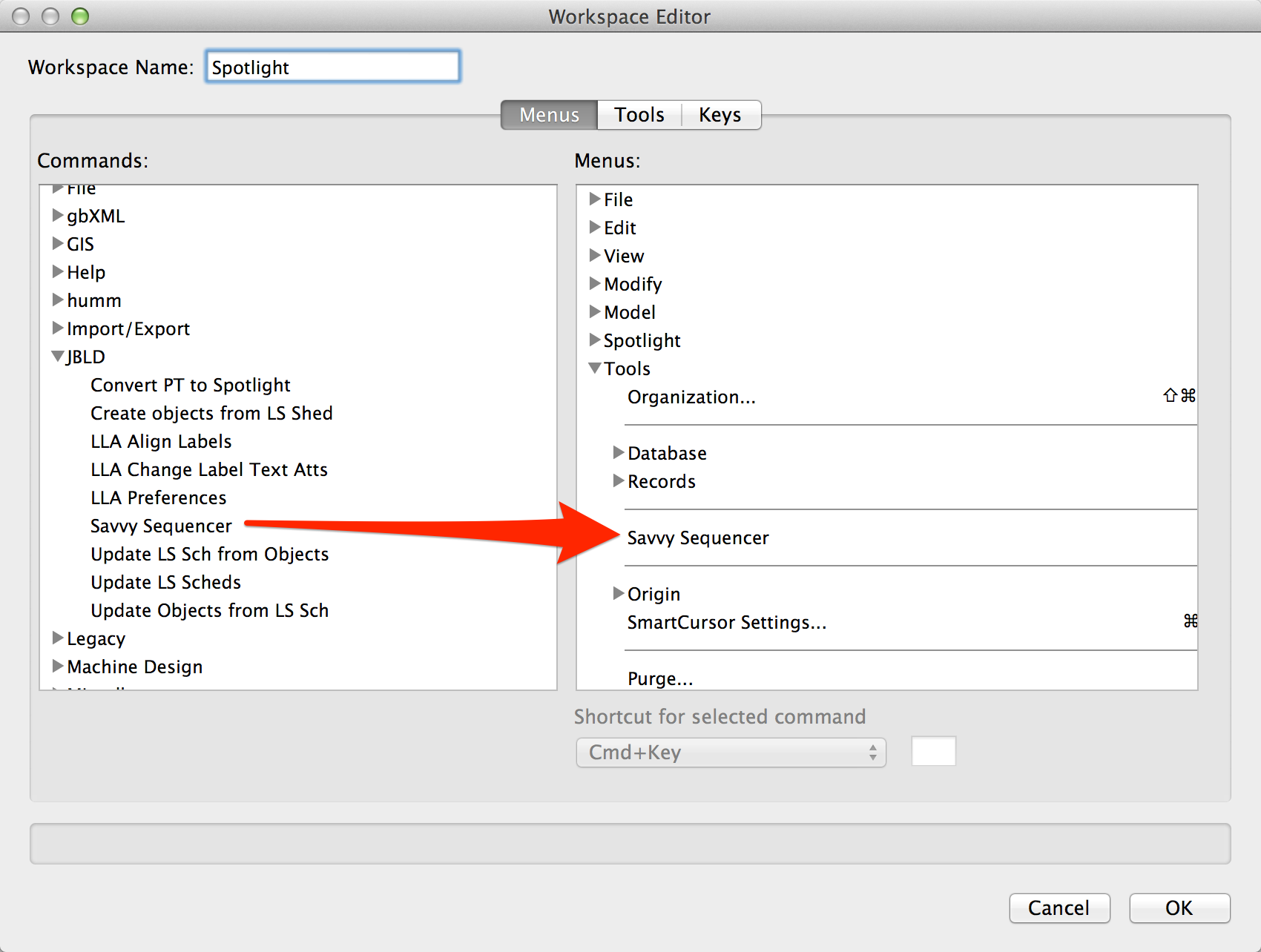
Adding to your workspace
-
Select Tools>Workspaces>Edit Current Workspace.
-
Click the disclosure triangle next to JBLD in the list of Menus categories on the left hand side.
-
Drag the “Add Savvy Position Labels…” menu command to the menu tree on the right side.
-
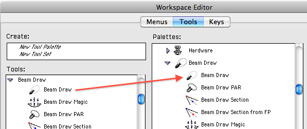
Select the Tools tab.
-
Click the disclosure triangle next to JBLD in the list of Tools categories on the left hand side.
-
Drag Savvy Position Label to an existing palette on the right or create a new palette.
-
Click OK.
Registration
The first time you use the Savvy Position Label, Vectorworks will ask you for a registration number or demo code. You can also access the registration dialog through the “About” button in the object’s Object Info palette. The Savvy Savvy Position Label will not draw without a valid code, however if you remove the Savvy Position Label plug-in from your user folder, you will still see all lineset objects but in a locked state. The Savvy Position Label is also part of the Savvy Subscription Series.
Overview
Insert the Savvy Position Label via the object tool or the included menu command. Labels can link to a Hanging Position for the label text and data displayed in the Label’s note, or you can enter custom text. A variety of display options are available in Object Info.
Placing in the drawing
The Savvy Position Label insertion tool
-
Select the Savvy Position Label insertion tool

-
If you want to immediately link the label to a Hanging Position or set an unlinked position location, make sure the Link Button
 is enabled in the mode bar.
 -
Optionally, select the Alignment parameter for the label in the mode bar. See Parameters.
-
Optionally, set the insertion alignment of the label. The origin of the label is the first character for Left Alignment, last character for Right, and center for Center.
-
Click in the drawing to insert the label and set the rotation.
-
If you selected the Link mode, you will see a line connecting the label to a place-link cursor. Click on a Hanging Position to set the link. You will see the Position Object highlighted and the cursor change as you hover over it with your mouse.

-
If you do not select a position while in Link mode, the point on which you click determines the position’s location, which appears in the label’s note and to which the label’s leader line points. This can be useful when identifying a boom location in plan view, for example.
The Add Savvy Position Labels menu command
-
Select Hanging Positions to which you want to add labels.
-
Select the Add Savvy Position Labels… menu command.
-
Select options in the dialog:
The position option sets the position of the label around the Hanging Position, as well as Alignment and Arrow Angle parameters so that the arrow points towards the Position.
The offset specifies the distance from the edge of the position to the insertion point of the label. A positive value measures away from the position in any direction.
Show options will raise the Label’s default parameters dialog before placing labels.

Linking to a Position
Linking Labels to Positions synchronizes the Label with the Position name and moves the label when you move or duplicate the position. Linked labels can also automatically display the Position’s Length, Trim (z height), Location field, and weight in the Label’s note.
Inserting Position Labels using the above methods link the Label to a Position.
To associate an existing Label with a Position, click the Set Link button in Object Info, or right-click on the label and choose Set Link… In the resulting dialog, select from a list of positions in the drawing, identified by name, or choose Click on drawing to select to exit the dialog and select a Hanging Position in the drawing.

To unlink a label from a position, use this dialog, or right-click on a label and select Unlink.
Object Parameters
As with all Plug-In Objects, the first time you place a Savvy Position Label object in a document, Vectorworks will ask you for default parameters. You can set the default object parameters for the document by selecting the object’s tool, then clicking on the parameters button  in the mode bar.

| Parameter | Description |
| Text Style | Pick a text style for the label. To set a default text style, use class options to set the text style by class. |
| Style | Use this menu to apply, create, or modify a Style definition for the label. Label styles appear as “red” symbols in the Resource Manager, and specifies whether parameters reference the style definition. For more information, see Concept: Plug-in Object Styles in Vectorworks help. |
| Hide Style Parameters | Enable this option to hide any parameters linked to a style definition. |
| Linked to | Read only field displaying the name of the position to which the label is linked. When you select a Position Label, you will also see a link icon in the drawing indicating the link. |
| Set Link | Raises a dialog where you can select a Hanging Position to link to the label. You can also opt to click on a position object or unlink the label from a position. |
| Alignment | Left / Center / Right: Determines the text alignment and arrow position for the label. |
| Move with position | Enable this to move the label as you move the position, as though they are grouped. Moving the label, however, does not move the position. |
| 3D Rotation | Enter a value for rotating the 3D component of the label around its horizontal axis. |
| 3D Only | By default, the Savvy Position Label is hybrid, with the label appearing both in plan view and at the z height of the position. The 3D component of the symbol can only rotate along its horizontal axis, so a typical label would then face forwards with a 90 degree 3D Rotation. Setting the label to 3D only allows the planar label to rotate to any 3D plane. In this mode, you do not see a 2D version of the label in Top / Plan. |
| Label | |
| Label Display | Determines how the position name displays in the label. Full: The full name. First word: The first word, before a space. E.g. “1 Electric” would be “1.” Last word: The last word, after a space. E.g. “A Pipe” would be “A.” Only Number: Extracts a number from the name. e.g. #4 Elec would be “4.” Custom: Ignores the position name and uses the text field below. If you do not link a label to a position, the object sets this option as default. |
| Cust. Label | Use with the Custom label display option to completely override the position’s name. |
| Prefix | Adds a prefix before the label text. |
| Suffix | Adds a suffix after the label text. |
| Shape | |
| Container | Circle / Rectangle / Rounded rectangle / None: Choose a container for surrounding the label. The circle container will surround the first or last character in left or right modes. |
| AutoFit | Fit the container to the label text. |
| Width | If AutoFit is disabled, specify the size of the container, in page units. |
| Padding | Add an additional amount of white space between the text and container, in page units. |
| Draw shadow | Add a drop shadow to the container. This is a distinct option from the drop shadow capability in Vectorworks 2017. |
| Arrow type | Triangle / Arrow / None / Symbol: Choose an arrow that points from the label to the position. You can also select no arrow and a custom symbol for the arrow. |
| Symbol | If you select the Symbol option above, specify the symbol here. This is a text field for ease of copy and paste. Use the button below to select a symbol resource. |
| Select symbol | Select from available symbols. |
| Arrow Angle | 90 / 0 / –90 / Custom: Sets the arrow straight, up, or down, depending on orientation. Select Custom to set an angle via the field below. |
| Cust. Angle | Enter a custom arrow if chosen above. |
| Arrow scale | Scale the arrow to refine the look of the label. A scale of 1 equals 100%. |
| Note | |
| Show note | Enable this to show a note below the label. |
| Text Style | Optionally, set a separate text style for the note. |
| Alignment | Choose to align the note consistently with the label or specify its own Left, Center, or Right alignment. |
| Wrap note | Enable this to wrap the note to the length of the container. |
| Fit container to note |
With this option enabled, the container grows to include the note text.
|
| Note | The note text. This field is for easy access and copy / paste. |
| Edit note |
Presents a dialog for editing the note. The note can be multiple lines and can insert tokens for X Coordinate, Y Coordinate, Distance from Centerline, SL/SR (depending on if the X coordinate is negative or positive), Location, Pipe Length, and Trim. X Coordinate, Y Coordinate, and Distance from Centerline take their data from the Label’s Position control point, which defaults to the Hanging Position’s insertion point. Move the control point or set the data fields below to specify any point in the drawing. Location takes its data from the Position’s Location field, which can store a lineset number or other location data. Pipe Length gets its data from the length of Lighting Pipe, Straight Truss, or Line geometry used for the Hanging Position. Trim gets its data from the Hanging Position’s z height. A setting can specify an offset for the display trim if trims are not measured to the stage floor. Weight gets its data from the Hanging Position’s Total Hung Weight field. |
| Rounding | Round the coordinate data by this value. |
| Auto position note | Enable this to automatically position the note below the label. |
| Leader Line | |
| Position X, Y | The coordinate of the position that displays in the note. This also corresponds to a control point in the drawing. If the label is linked to a position and set to move with the position, this coordinate will adjust as you move the position. |
| Draw leader to position | Draws a leader line from the label to the position coordinate. |
| Leader type | Straight / Bezier / Shoulder: Choose the type of leader line. |
| Draw symbol at endpoint | Add a symbol to mark the position location, for example a boom marker or rigging point. |
| Symbol Name | The name of the symbol. This field is provided for ease of copy / paste. |
| Symbol Rot | Rotation of the position marker symbol. |
| Select symbol | Choose an available symbol resource for the position marker. |
| Classes | |
| Auto-Class | Enable this to class each component with default class names. The prefix for subclasses can be determined in settings. |
| Container Class | Class for the container geometry. |
| Arrow Class | Class for the arrow. If no by-class options exist for the arrow, it will fill solid black. |
| Shadow Class | Class for the container drop shadow. |
| Leader Class | Class for the leader line. |
| Note Class | Class for the note text. |
| Update | Any changes to the Hanging Position that affect the Savvy Position Label text, placement, or note should automatically update the Label, but this button will force an update to catch any unreflected changes. |
| Settings… |
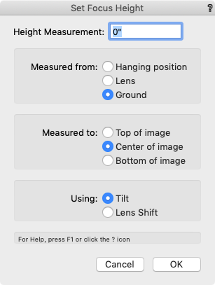
Set settings that affect all Savvy Position Label Objects Default insertion class: Choose a class for new Label objects. You can also opt to insert labels in the active class. Component class prefix: Enter a base class name that the Auto-Class option will use to build class names. Trim offset: Enter an offset for the trim display, for example to display trims above a show deck height, with this value subtracted the Hanging Position’s Z height. Note, the trim starts at the layer’s elevation. Make default for all new documents: Select this option for these settings to be default values for all future new Vectorworks documents. |
| About | See version and registration information |


Known Issues
-
Adding special fields to the note text makes use of the clipboard. After exiting the dialog, the special field token may remain on the clipboard.
FAQ
###


 The channel displays at the focus point. You can change the font and size using the Text menu.

 Shows the full coverage of a beam from one cut plane to another. Showing from Face Plane to Floor Plane, for example, will show you the area of full body coverage. The options are:
 The Interactive Shutter Angles dialog lets you control shutter depths and angles with interactive sliders.


 assumes that the drawing origin is your plaster or setting line. In this mode, your first click will be on lineset 1. The second mode
  lets your first click designate the zero point for distance measurements.
